


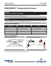

5
Instruction Manual 402 and 402VP
LIQ_MAN_ABR_402_402VP January 2014
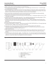
GRAY
ORANGE
RED
RED
CABLE
SENSOR
WIRES
GRAY
CLEAR
WHT/RED
CLEAR
RED
WHITE
ORANGE
CLEAR
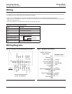
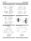
Figure 6. Wiring for Sensor-Mounted Junction Box Figure 7. Wiring for 54eC and 54C
Wiring
Note
For additional wiring information on this product, including sensor combinations not shown here, please refer to either our online
wiring programs or the Manual DVD enclosed with each product.
1056, 1057, 56, 5081, 6081, 54e, and XMT : http://www3.emersonprocess.com/raihome/sp/liquid/wiring/XMT/
1066 and sensors with SMART preamps: http://www2.emersonprocess.com/en-US/brands/rosemountanalytical/Liquid/Sensors/
Pages/Wiring_Diagram.aspx
1055: http://www3.emersonprocess.com/raihome/sp/liquid/wiring/1055/
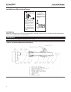
Wire Color and Connections in Sensor
Color Function
Gray Connects to outer electrode
Clear Coaxial shield for gray wire
Orange Connects to inner electrode
Clear Coaxial shield for orange wire
Red
White with red stripe
White
Clear Shield for all RTD lead wires
Wiring Diagrams
Note: Terminals in junction
box are not numbered.
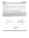
RTD
RTD in
RTD sense
RTD return
CLEAR
WHITE
WHITE/RED
RED
CLEAR
ORANGE
CLEAR
GRAY
GROUND
RTD SHIELD
RTD RETURN
RTD SENSE
RTD IN
N/C
RECEIVE COMMON
RECEIVE
N/C
DRIVE COMMON
DRIVE
GROUND
SENSOR CABLE
MODEL 54C & 54eC
ANALYZERS
TB1
TB