


7
Instruction Manual 402 and 402VP
LIQ_MAN_ABR_402_402VP January 2014
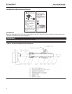
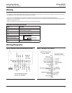
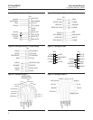
Wiring through a Junction Box
If wiring connections are made through a remote junction box (PN 23550-00), wire point-to-point. Use interconnecting
cable 23747-00 (factory-terminated) or 9200275 (no terminations).
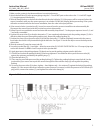
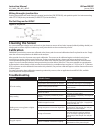
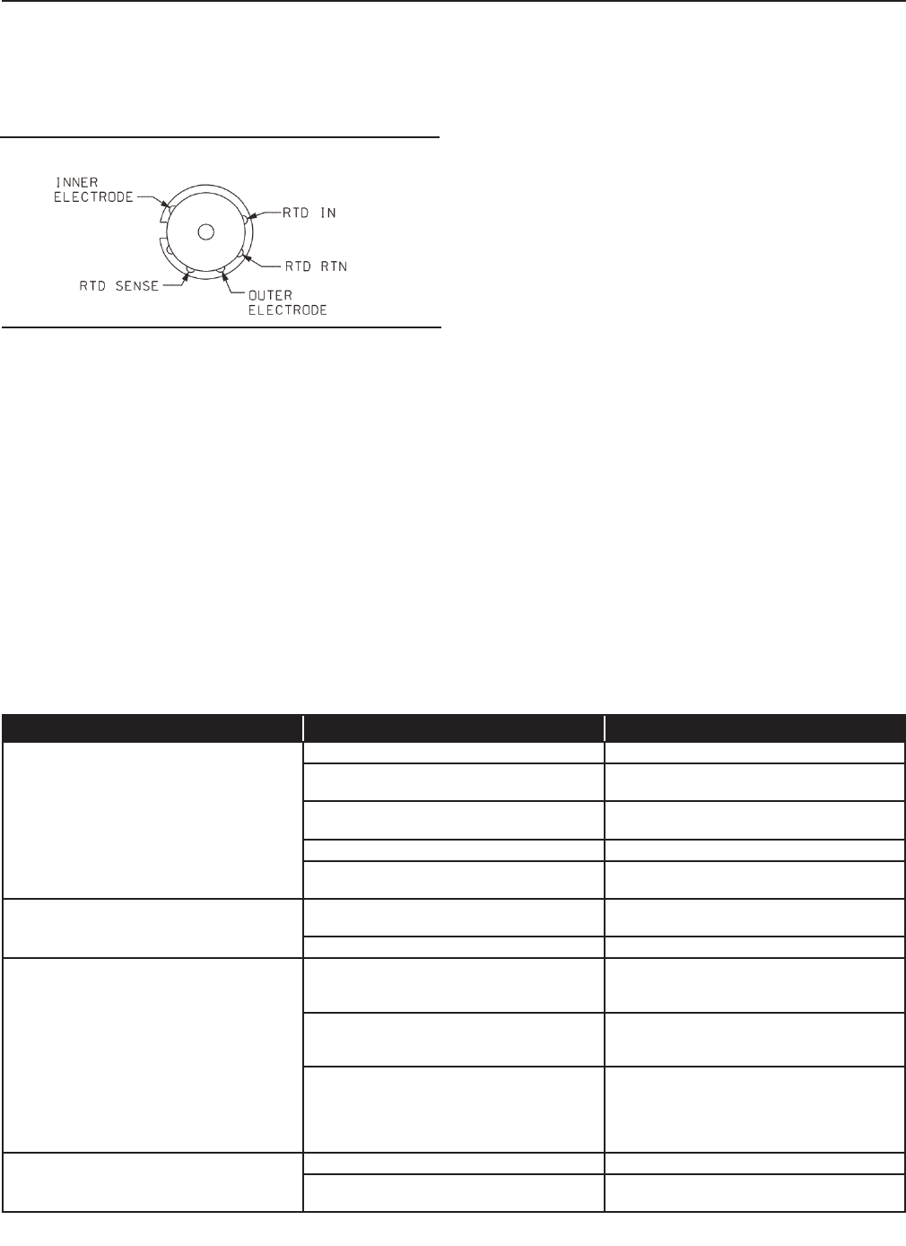
Pin Out Diagram for 402VP
Figure 14. VP pin-out
Cleaning the Sensor
Use a warm detergent solution and a soft brush or pipe cleaner to remove oil and scale. Isopropyl alcohol (rubbing alcohol) can
also be used to remove oily lms. Avoid using strong mineral acids to clean conductivity sensors.
Calibration
ENDURANCE conductivity sensors are calibrated at the factory and do not need calibration when rst placed in service. Simply
enter the cell constant printed on the label into the analyzer.
After a period of service, the sensor may require calibration. The sensor can be calibrated against a solution having known
conductivity or against a referee meter and sensor. If using a standard solution, choose one having conductivity in the
recommended operating for the sensor cell constant. Refer to the analyzer manual or product data sheet for recommended
ranges. Do not use standard solutions having conductivity less than about 100 uS/cm. They are susceptible to contamination
by atmospheric carbon dioxide, which can alter the conductivity by a variable amount as great as 1.2 uS/cm (at 25 °C). Because
0.01/cm sensors must be calibrated in low conductivity solutions, they are best calibrated against a referee meter and sensor in
a closed system.
For more information about calibrating contacting conductivity sensors, refer to application sheet ADS 43-024, available
on the Rosemount Analytical website.
Troubleshooting
Problem Probable Cause Solution
Off-scale reading
Wiring is wrong. Verify wiring.
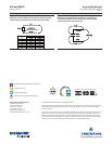
Temperature element is open or shorted.
Check temperature element for open or
short circuits. See Figure 15 (next page).
Sensor is not in process stream.
Be sure sensor is completely submerged in
process stream.
Variopol cable is not properly seated. Loosen connector and reseat.
Sensor has failed.
Perform isolation checks.
See Figure 16 (next page).
Noisy reading
Sensor is improperly installed in process
stream.
Be sure sensor is completely submerged in
process stream.
Variopol cable is not properly seated. Loosen connector and reseat.
Reading seems wrong (lower or higher
than expected
Bubbles trapped in sensor.
Be sure sensor is properly oriented in
pipe or ow cell. See Figure 1. Apply back
pressure to ow cell.
Wrong temperature correction algorithm.
Check that temperature correction is
appropriate for the sample. See analyzer
manual for more information.
Wrong cell constant.
Verify that the correct cell constant has
been entered in the analyzer and that
the cell constant is appropriate for the
conductivity of the sample. See analyzer
manual.
Sluggish response
Electrodes are fouled. Clean electrodes.
Sensor is installed in dead area in piping.
Move sensor to a location more
representative of the process liquid.