


4-3
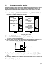
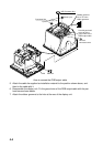
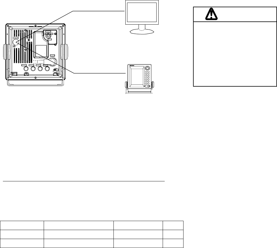
4.2 Connection of External Monitor/Remote Display
The above units can be connected to the MODEL1833/1933/1943 by using the hole at the
rear of the display unit. Remove the connector cover to use this hole. After connecting,
cover the hole with soft putty to seal the hole.
VGA monitor
Remote display (ex. FMD-811)
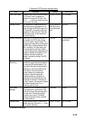
CAUTION
Even though the display
unit meets waterproof
standard IPX-5,
this modification can
affect waterproofness.
Watertight integrity
cannot be guaranteed.
Connection of External monitor/remote display
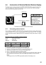
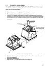
4.2.1 Connecting external monitor
You can display the MODEL1833/1933/1943 screen on the external monitor, which accepts
industrial standard VGA input by using the optional RGB output cable kit OP03-176. Supply
monitor and interconnection cable (with HD-15P connectors of male, three rows of 15 pins)
locally.
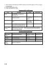
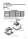
Necessary parts for connecting of external monitor
Name: RGB output cable kit
Type: OP03-176
Code No.: 008-526-360
Name Type Code No. Qty
Cable assy. 15SDS/XHP10-005 000-144-511 1
Grommet MG-4 000-871-378 1
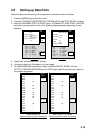
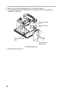
1. Unscrew six connecter nuts at the rear of the display unit.
2. Unfasten 16 binding screws (M3x10) to remove the display cover.
3. Remove the connector cover at the rear of the display cover.
4. Cut a “x” in the rubber grommet to pass the cable.
5. Pass the RGB output cable through the rubber grommet (supplied with option) hole and
then connect the XH connector (10P) of the RGB output cable to J106 on the SPU
Board.
Put the ground wire of the RGB output cable outside of the display cover.