


29
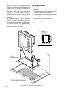
¡ The compass safe distance should be ob-
served to prevent deviation of the magnetic
compass.
ssapmocdradnatSssapmocgnireetS
m9.0m7.0
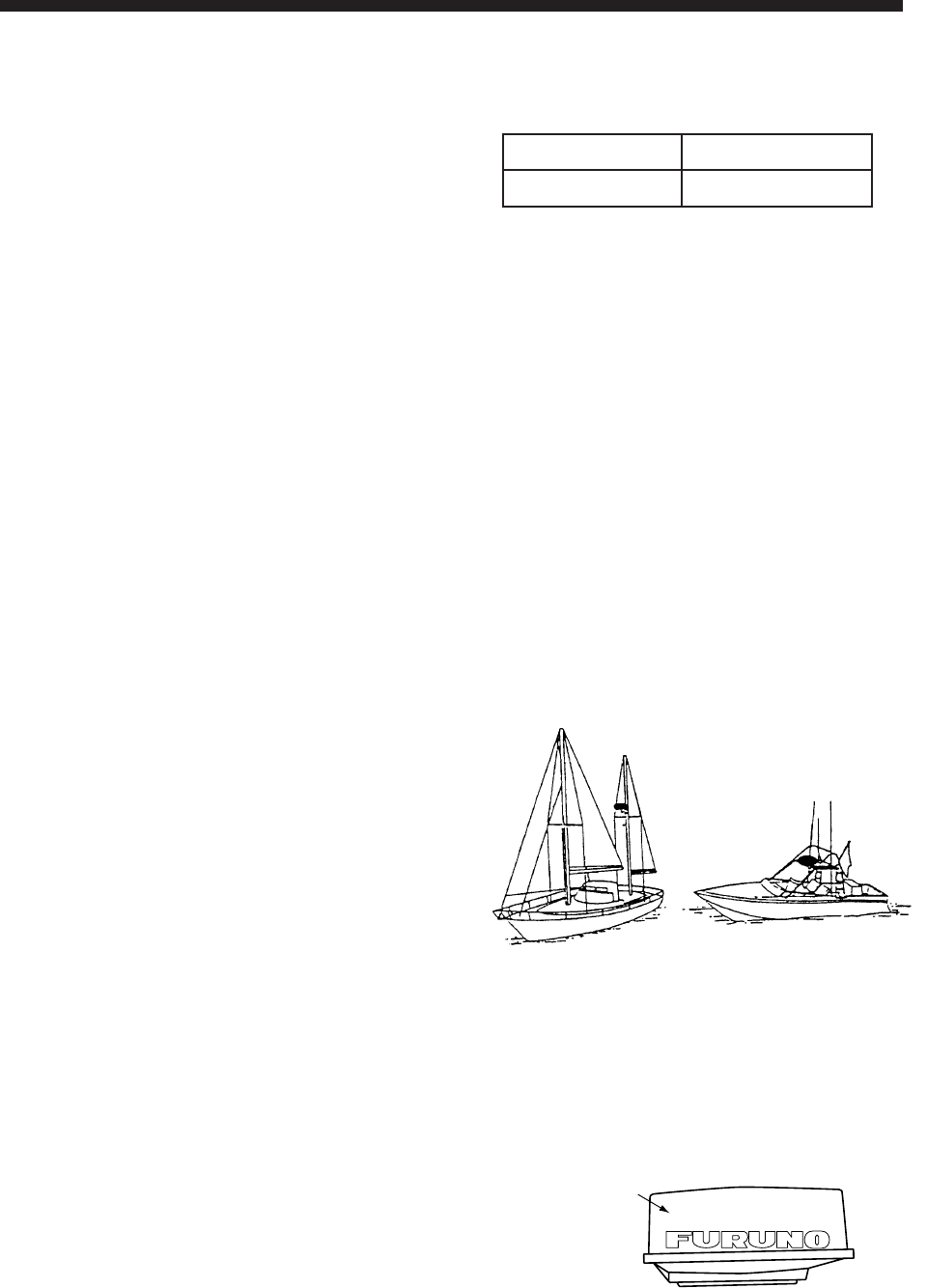
¡ Do not paint the radome to ensure proper
emission of the radar waves.
¡ When this radar is to be installed on larger
vessels, consider the following points:
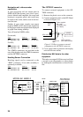
(1) The signal cable run between the antenna
and the display comes in lengths of 10
m, 15 m, 20 m and 30 m. Whatever
length is used it must be unbroken;
namely, no splicing allowed.
(2) Deposits and fumes from a funnel or
other exhaust vent can adversely affect
the aerial performance and hot gases
may distort the radiator portion. The an-
tenna unit must not be mounted where
the temperature is more than 70°C.
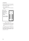
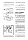
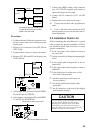
Mounting
Figure 5-1 Typical antenna unit location
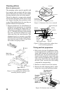
Unpacking the antenna unit
1. Open the antenna unit packing box carefully.
2. Unbolt the four bolts at the base of the ra-
dome to remove the radome cover.
Radome cover
Figure 5-2 Antenna unit
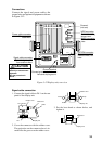
5. INSTALLATION
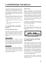
This chapter provides the procedures neces-
sary for installation. Installation mainly con-
sists of the following:
¡ siting and mounting the display unit and
antenna unit
¡ connection of the signal cable and the power
cable
¡ establishing the ground
¡ checking the installation, and
¡ adjustments.
5.1 Antenna Unit Installation
Siting, handling considerations
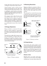
¡ The antenna unit is generally installed either
on top of the wheelhouse or on the radar mast
on a suitable platform. Locate the antenna
unit where there is a good all-round view rig-
ging intercepting the scanning beam. Any
obstruction will cause shadow and blind sec-
tors. A mast for instance, with a diameter
considerably less than the width of the
radicator, will cause only a small blind sec-
tor, but a horizontal spreader or crosstrees in
the same horizontal plane as the antenna unit
would be a much more serious obstruction;
you would need to place the antenna unit well
above or below it.
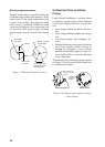
¡ It is rarely possible to place the antenna unit
where a completely clear view in all direc-
tion is available. Thus, you should determine
the angular width and relative bearing of any
shadow sectors for their influence on the ra-
dar at the first opportunity after fitting. (The
method of determining blind and shadow
sectors appears later in this chapter.)
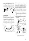
¡ If you have a radio direction finder on your
boat, local its antenna clear of the antenna
unit, to prevent interference to the direction
finder. A separation of more than two meters
is recommended.
¡ To lessen the chance of picking up electrical
interference, avoid where possible routing
the signal cable near other onboard electri-
cal equipment. Also avoid running the cable
in parallel with power cables.