


32
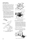
• Make sure you allow enough clearance
both to get to the connectors behind the unit
and to allow you to get your hands in on
both sides to loosen or tighten the mount-
ing knobs. Make sure you leave at least a
foot or so of “service loop” of cables be-
hind the unit so it can be pulled forward
for servicing or easy removal of the con-
nectors.
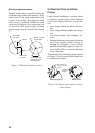
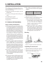
• A magnetic compass will be affected if
placed too close to the display unit. Ob-
serve the minimum compass safe distances
to prevent deviation of a magnetic com-
pass: standard compass, 0.7 meters, and
steering compass, 0.5 meters.
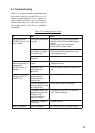
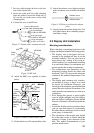
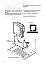
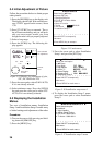
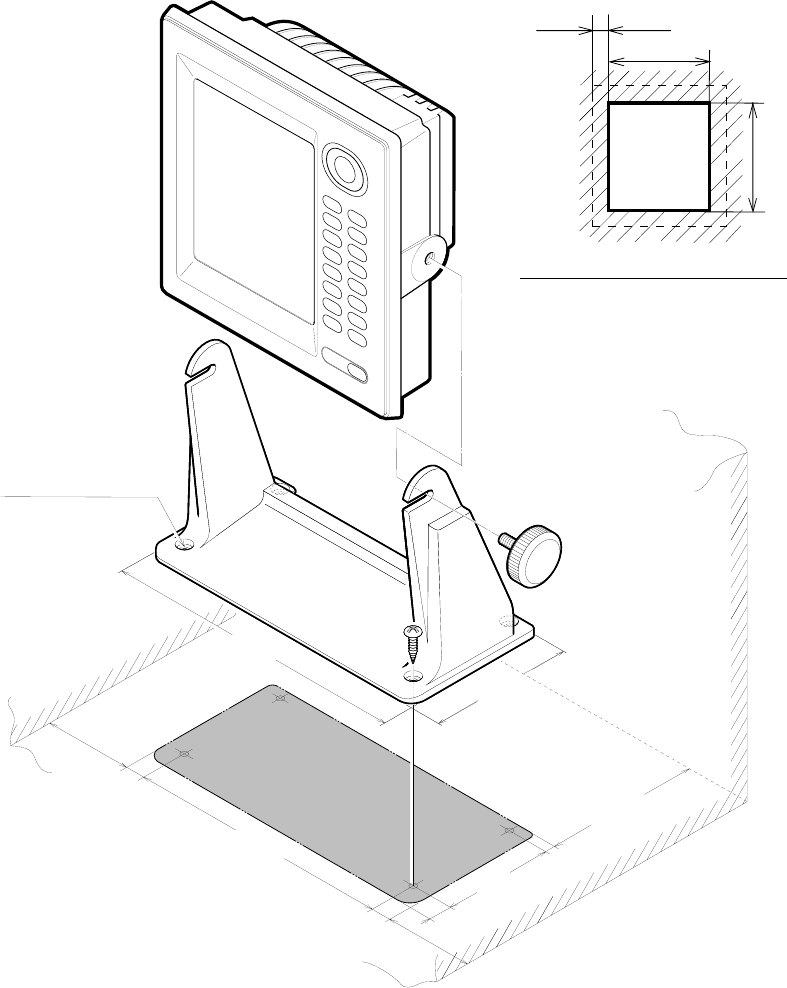
Mounting procedure
The display unit is designed to be mounted
on a tabletop.
1) Using the hanger as a template, mark screw
locations in the mounting location.
2) Fix the hanger to the mounting location with
four M6 tapping screws (supplied).
3) Fit the knob bolts to the display unit.
4) Install the display unit in the hanger.
5) Tighten the knob bolts securely.
*140
(5.51")
10
(0.39")
238
(9.37")
18
(0.71")
18
(0.71")
*80
(3.15")
*80
(3.15")
100
(3.94")
20
(0.79")
274
(10.79")
130
(5.12")
4 -
ø6
FIXING HOLES
*
:SERVICING CLEARANCE
10mm
222(8.7")
236(9.3")
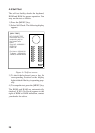
Cutting size for flushmount
Figure 5-11 How to mount the display unit