


31
7. Pass the cable through the hole at the bot-
tom of the radome base.
8. Secure the cable with the cable clamping
plate and gasket. Ground the shield and vi-
nyl wire by one of the screws of the cable
clamping plate.
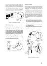
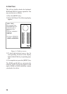
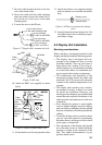
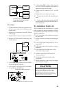
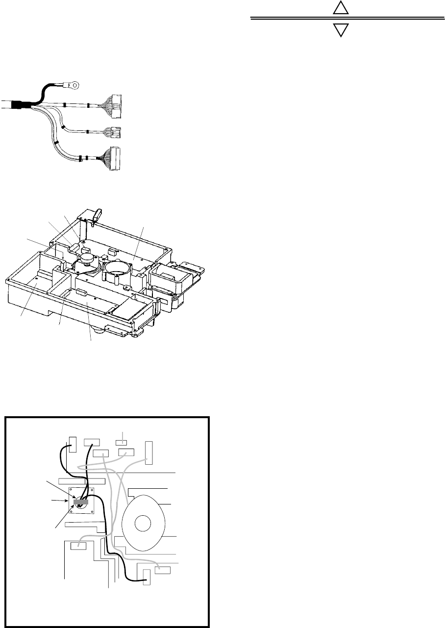
9. Connect the wire to the RF unit.
to one of the screws
of the cable clamping plate
9-pin connector:
to J801 on MD-9208
4-pin connector:
to J802 on MD-9208
13-pin connector:
to J611 on IF-9214
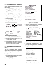
Figure 5-7 Signal cable, antenna unit side
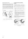
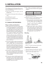
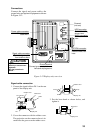
J802
J801
J611
MD-9208
IF-9214
PTU-9335
Cable
entry
Figure 5-8 RF unit
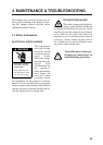
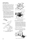
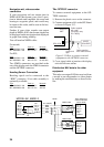
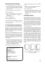
10. Attach the EMC core supplied as shown
below.
J806
J805
J803
J804
J802
J801
Motor
J613
J611
J1
EMC core
E04SS251512
(Above cable
clamping
plate)
Cable
entrance
IF9214
PTU-9335
MD9208
Cable
clamping
plate
Figure 5-9 How to attach EMC core
11. Fix the shield cover. Do not pinch the cable.
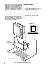
5.2 Display Unit Installation
Mounting considerations
When selecting a mounting location for the
display unit keep in mind the following points.
• The display unit is designed and con-
structed to be splashproof, thus it can be
installed outdoors. You can even hose it
down after a day’s outing. If it is to be in-
stalled outdoors, we recommend installing
it an enclosed cabinet, for maximum pro-
tection against the marine environment.
• The temperature and humidity of the
mounting location should be stable and
moderate. No LCD can provide adequate
contrast if the ambient temperature is too
extreme.
• The display unit consumes only a moder-
ate amount of power, so there is no need
for forced air ventilation. However, you
should provide adequate space behind and
around the unit to permit circulation of air
and to provide convenient access to the rear
connectors.
• Even though the picture is quite legible
even in bright sunlight, keep the display
unit out of direct sunlight or at least shaded
because of heat that can build up inside the
cabinet.
• Locate the display unit in a position where
you can view and operate it conveniently
but where there is no danger of salt or fresh
water spray or immersion.
• The orientation of the display unit should
be so the radar screen is viewed while the
operator is facing in the direction of the
bow. This makes determination of your
position much easier.
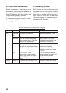
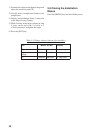
12. Attach the radome cover, aligning triangle
mark on radome cover with that on radome
base.
Radome cover
Radome base
Figure 5-10 How to position the radome
cover
13. Loosely fasten the radome fixing bolts. You
will tighten them after confirming magne-
tron heater voltage.