


15-1
INPUT DATA SELECTION
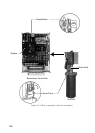
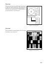
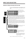
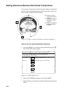
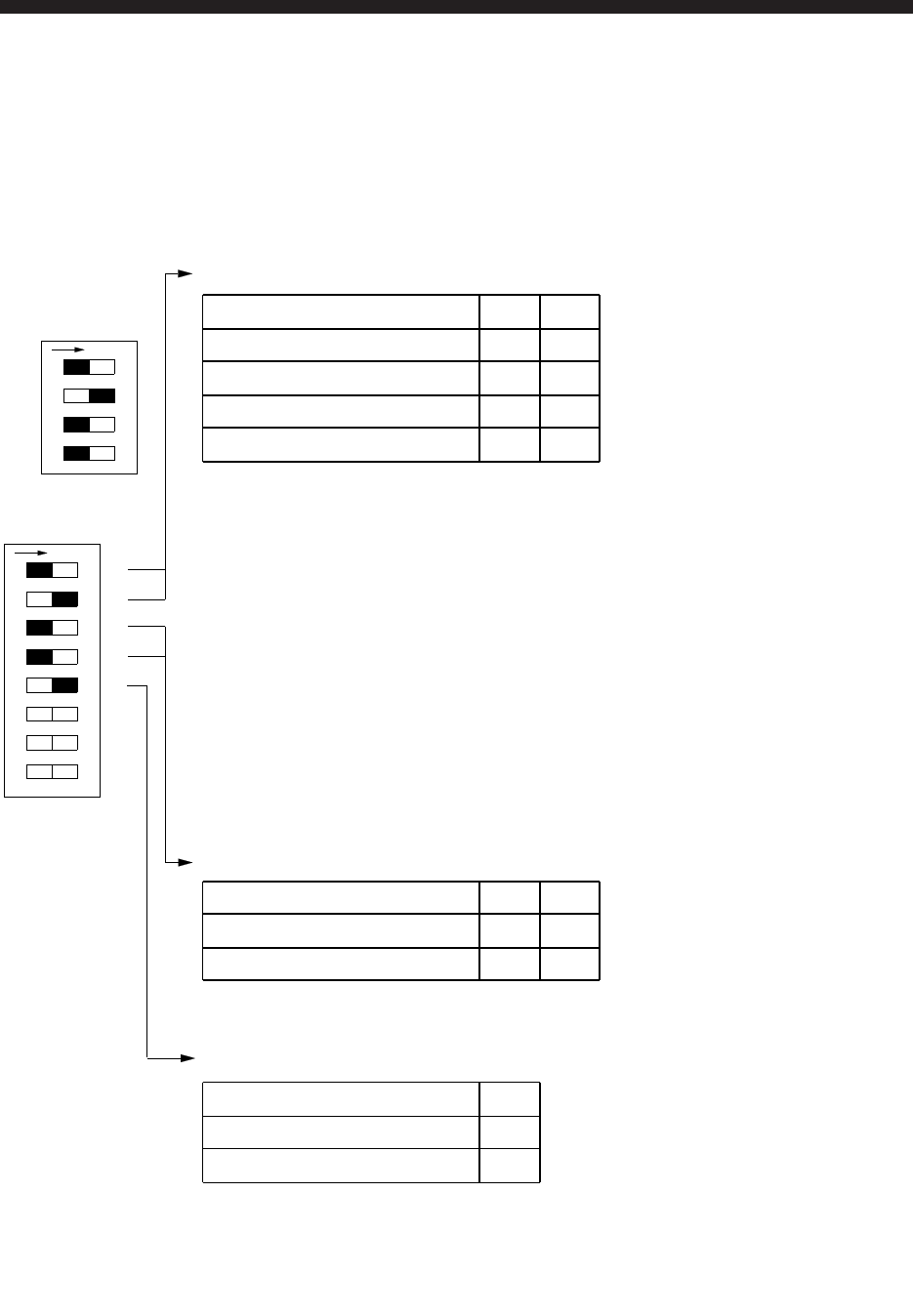
Selection of Data at Interface Unit CS-120A
Nav data and fish data input from external equipment can be
turned on or off at DIP switch DP-1 in the Interface Unit CS-
120A.
Ship's speed and bearing (for track plotting, true motion, target lock, etc.)
Input Device S1 S2
Select navigation which feeds
nav data for drawing ship's track
by switch S1 and S2.
Gyrocompass, Speed log OFF OFF
GPS or DR (Note 1) ON OFF
Current Indicator OFF ON
DR or Current Indicator (Note 2) ON ON
Note 1: GPS has priority. Switched automatically from GPS to DR when
GPS data is absent for more than 61 seconds or ship's speed measured with
GPS is 0.2 kts or less. If DR is not available when switched from GPS to
DR, heading readout is fixed at 0 degrees and ship's track is plotted by using
the last GPS data obtained before switching to DR. If you still require speed,
heading data from GPS even though ship's speed is less than 0.2 kts, set the
GPS format to DR. Note however that the heading direction becomes erratic
if the ship's speed is less than 0.2 kts.
Note 2: Use this setting when both DR and current indicator are available.
Normally DR data has highest priority, and is switched to current indicator
data if the DR data is absent for more than 61 seconds. The heading data for
the bearing scale is always provided from the current indicator. When DR
data is taken from GPS be sure to set GPS output format to "DR." GPS with
no "DR" output format cannot be used.
Ship's Position
Input Device S3 S4
Use this position for GPS or DR.
GPS data has priority.
Loran C OFF OFF
GPS or DR (See Note.) ON OFF
Depth (echo sounder, color video sounder, etc.)
Input Device S5
Note 1: For white line pulse when the
depth data is taken from an echo
sounder which does not have digital
depth output.
Note 2: When the depth data is taken
from an echo sounder which has digital
echo output (FE-822, FCV, ED-202,
IF-3000, or IF-5000).
Echo Sounder (Note 1) OFF
GPS or DR (Note 2) ON
S1
12345678
S2
S3
S4
S5
1234
ON
Standard
setting
ON
Figure 15-1 DIP switch settings in the interface unit