


654321
FURUNO ELECTRIC CO., LTD.
A
B
C
D
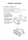
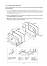
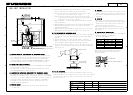
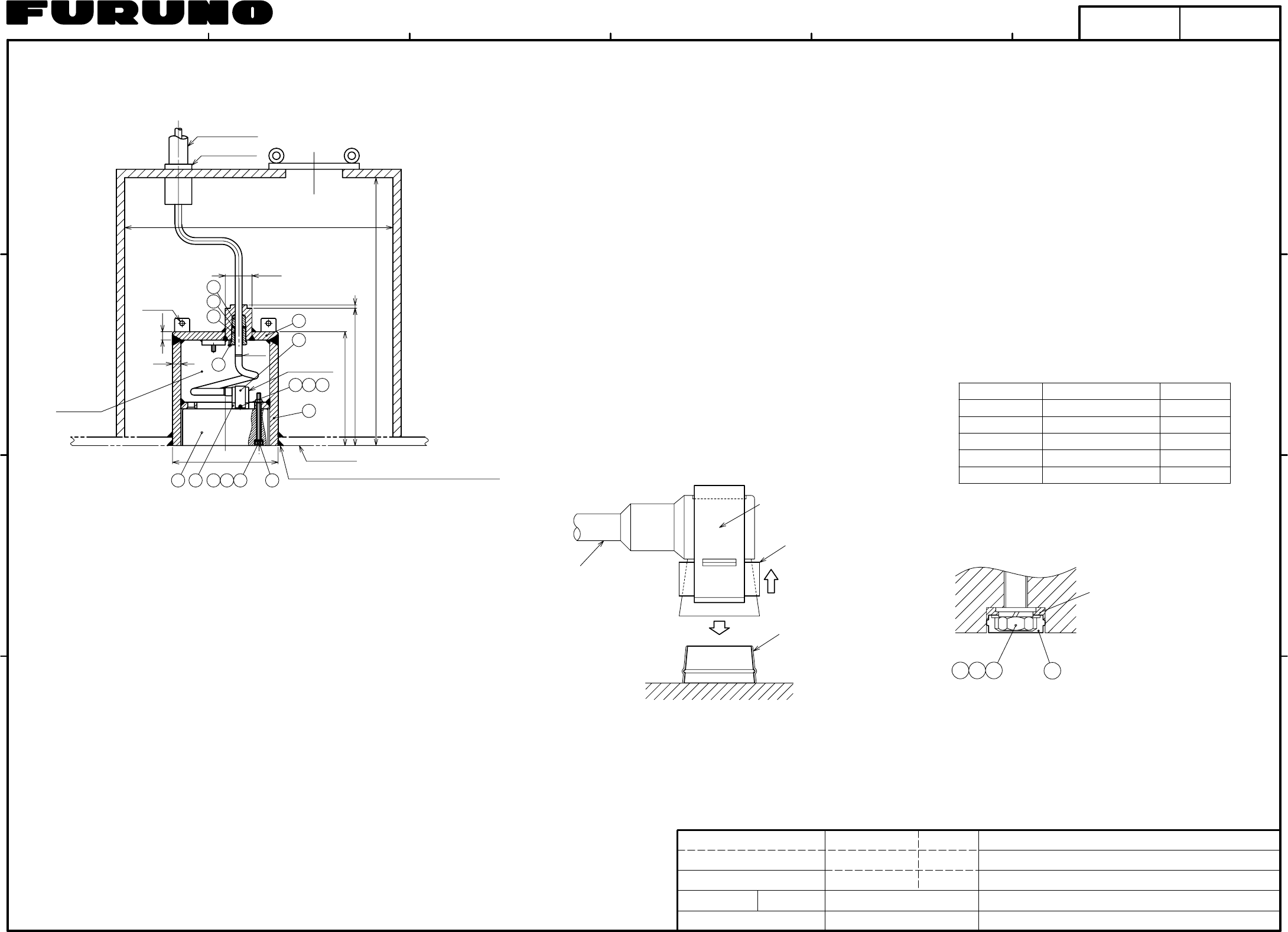
HULL UNIT INSTALLATION
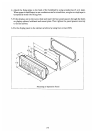
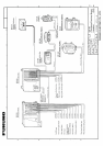
⑥ Connector Holder
Ring
Silicone Grease
(Thine Coating)
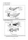
Twisting the cable (namely, rotating the transducer by about one turn),
align the bow mark on the transducer with ship's bow and fix the transducer
450~550
450~550
0.5~3.0
0.5~3.0
0.5~3.0
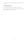
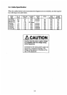
STANDARD(Ω)
BEAM 2 (RED)
BEAM 3 (GRN)
TEST POINT
BEAM 1 (BLK)
TEMP SENSOR 1
TEMP SENSOR 2
TB #1(RED) - #2(BLK)
TB #4(RED) - #5(BLK)
TB #7(RED) - #8(BLK)
TB #10(YEL) - #11(WHT)
TB #13(BLU) - #14(GRY)
TYPE OF SIGNAL
Before starting the installation work, check that the transducer casing
is of a material approved by ship classification society concerned and
with a thickness not thinner than the hull plate. The standard tank
supplied by FURUNO is of material KSTPG370(KSTPG38,KST138), approved
by ship Classification Society of Japan, with a thickness of 25 mm.
Select the installation site reffering to the recommended sites described
in the installation instructions.
For ships prone to collect air bubbles under the hull bottom, consult
your local FURUNO office or agent for advice.
law because the transducer casing is waterproof. However it is recommended
shipyard may change as required. Since the transducer is detachable/
replaceable in water from outside the ship, maintenance space is not
required inside the compartment.
fore-aft line.
a) Fore/aft marks are engroved on the casing. Align them with ship's
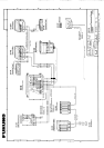
φ315
5
2-φ15
10
2
7
8 9
25
25
15
3
4
φ80
800
800
340
410
10
1112
1 14 13
CONDUIT PIPE
CABLE GLAND
CONNECTOR
WATERTIGHT
16
6
GROOVE DEPTH TO BE DETERMINED BY SHIPYARD.
(GRIND WELDING BUILD UP.)
HULL PLATE
※1※1
LINE
Cable
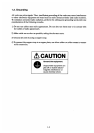
Comfirm the ohm value of terminals on the transducer.
Do not use a megohmmeter.
A digital ohmmeter is recommended.
1) CHECKING MATERIAL AND THICKNESS OF TRANSDUCER CASING
2) DETERMINING INSTALLATION SITE
3) CONSTRUCTING WATERPROOF COMPARTMENT FOR TRANSDUCER CASING
4) WELDING CASING
6) FIXING TRANSDUCER
9) TESTING AFTER INSTALLATION
The compartment for the transducer casing is not compulsory required by
to construct it for safety. Dimensions shown above are only for reference;
b) Orientation and leveling errors can be offset on the data offset
Fore-aft orientation: Align the bow mark on the casing with ship's
Leveling: Install the casing so that the top face of the casing
is horizontal during navigation. Measure leveling accuracy with
fore-aft line to an accuracy within 1 degree.
a level meter, after the ship is launched.
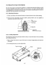
c) Detach transducer (1), cable, cable gland (5) and gasket (3) before
d) Welding method for casing and ship's hull should be determined by the
considers them necessary.
shipyard. Weld reinforcement ribs to the casing if the shipyard
welding the casing.
menu in the display unit. Install the casing as follows.
e) Remove welding build up between the casing and the ship's hull (part
supplied.
c) Remove dirt and apply silicone grease onto the side of receptacle
on the transducer before plugging the watertight connector.
d) To plug in the watertight connector, pull up the ring and insert the
connector into the receptacle, and then fix the connector holder (6)
with hex nut (7).
Lay the cable from the casing to the transceiver unit
inside a conduit pipe and fill the conduit pipe with
sand or other appropriate materials to prevent cable
vibration.
Shop primer coating (Epcom Zinc Rich Primer B) has
been applied to the casing. Paint both inner and outer
b) Install locking bolt (15) after the cable gland is tightened.
a) Lead the transducer cable into the casing up to the white line mark on
the cable and tighten the cable gland with the cable gland spanner
marked ※1 in the drawing) with a grinder, for a flat finish.
5) FIXING/CONNECTING TRANSDUCER CABLE
8) PAINTING
7) CABLING
surfaces on the casing with the paint used for top
coating of the ship's hull bottom.
SEE NOTE2
NOTE 1: The transducer surface is coated with anti-
fouling paint Marine Star 20. Do not coat it by other
type of paint.
NOTE 2: The inside of transducer tank (16) and
It has no problem.
bolt(10)-thru hole will be filled with water.
10
1112
DETAIL FOR FIXING BOLT AND BOLT CAP
13
kg
INSTALLATION PROCEDURE
DS-330/331
HULL UNIT
DS-30
E7236-Y10- J
Jul. 26 '06
Jul. 26 '06
T.TAKENO
T.YAMASAKI
CHECKED
APPROVED
DWG No.
DRAWN
SCALE
MASS
TITLE
REMARKS
NAME
by using hex bolt (10). After apply silicone sealant to bolt-head, put
SILICONE SEALANT
bolt cap (13) onto it.
2-6