


3-7
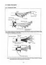
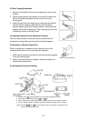
3) Wire Crimping Procedure
1. Strip the vinyl sheath of the wire to expose the core by 3mm
to 4mm.
2. Hold the crimping tool horizontally and insert the contact pin
with its slit faced downward into the crimp hole on the
crimping tool.
3. Insert the wire onto the contact pin and squeeze the handle
until the ratchet releases. Note that the wire should be
inserted deep enough until its end comes in contact with the
stopper plate of the crimping tool. After crimping, pull the wire
to make sure that it is securely fixed.
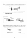
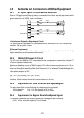
4) Inserting Contact Pin into Connector Housing
The connect pins fitted to wires should be inserted into the
connector housing referring to the interconnection diagram.
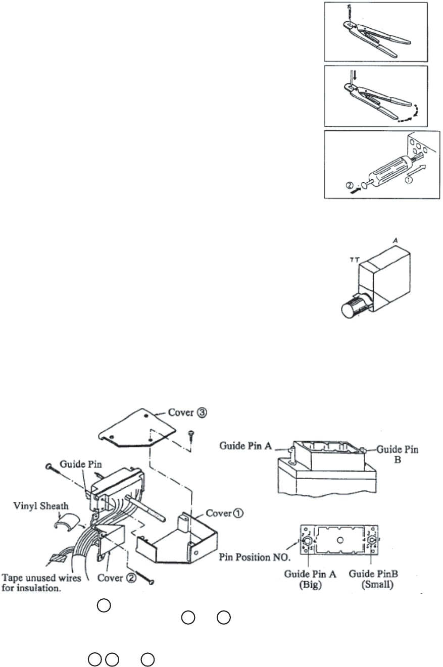
5) Procedure to Extract Contact Pin
When a contact pin is inserted into an incorrect hole on the
connector body, take it out by using the pin extractor.
1. Push the pin extractor into the pin hole from the side opposite
to the pin inserting side.
2. Push in the head of the pin extractor, and the contact pin is
unlocked and pushed out.
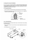
6) Assembling Connector Housing
Note) Covers 1 , 2 and 3 are not fitted on the connectors connected to the
main and sub display units.
1. Fix the cover 1 , paying attention to the cable outgoing direction.
2. Dress the wires and put covers 2 and 3 on.
3. Use a fragment of cable sheath to fix the wires with the connector clamp.
4. Cut the unused wires to proper length and wrap their ends with vinyl tape.
Cable out going direction