


3-11
3.4 Remarks on Connection of Other Equipment
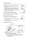
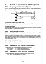
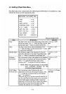
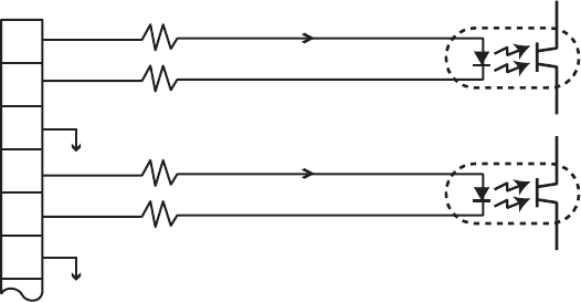
3.4.1 KP input Signal for Interference Rejection
When a TX trigger pulse (Keying Pulse) is connected from other acoustic equipment which
gives interference to DS-30, note the following.
1
2
3
4
5
6
TB3
External KP1
4mA
4mA
22Ω
22Ω
22Ω
22Ω
External KP2
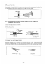
1) Interference Rejection Signal Input Circuit
Two iuput ports are provided in the processor unit for connection of KP for interference
rejection. Use any one of them.
2) Current Requirement
Recommended current is 4 mA while the circuit operates normally at 2 mA to 20 mA. Adjust
output resistance for the recommended current.
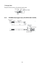
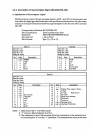
3.4.2 NMEA/CIF Signal I/O Circuit
The I/O circuit for NMEA or CIF format data has the configuration shown below, where CIF
is Furuno standard data format.
Maximum allowable current in NMEA output is 25 mA and recommended current is 10 mA.
When terminating the line by a photo-coupler for a current loop configuration, take suitable
means at the signal receiving side to limit the current. If, for example, forward voltage drop
in the photo-coupler is 2.2V:
[4.8 – 2.2 (V)]/[10(mA)] – 227 (Ω) = 33 (Ω)
therefore, 33 ohm resistor should be inserted in series in the line.
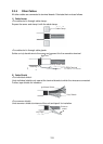
3.4.3 Requirement of Wind Direction and Speed Signal
The wind meter that outputs following dc voltages can be connected.
-Wind direction: 0 to 1 Vdc for direction of 0° to 540°
-Wind speed: 0 to 1 Vdc for speed of 0 to 60 m/sec
3.4.4 Requirement in Engine Revolution Speed Signal
The engine tachometer that outputs following dc voltage can be connected.
0 to 1 Vdc for revolution speed of 0 to full scale.