


iii
TABLE OF CONTENTS
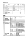
Complete Set........................................................................................................................ 1
Installation Materials ............................................................................................................. 3
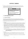
CHAPTER 1. GENGERAL .................................................................................1-1
1.1 Selecting Mounting Location......................................................................................1-1
1.1.1 Transducer (Hull Unit) .....................................................................................1-1
1.1.2 Other Indoor Units...........................................................................................1-2
1.2 Grounding..................................................................................................................1-3
CHAPTER 2. MOUNTING..................................................................................2-1
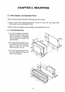
2.1 Display Unit and Operation Panel..............................................................................2-1
2.1.1 Standard Mounting ..........................................................................................2-1
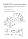
2.1.2 Mounting with Fixing Plate...............................................................................2-2
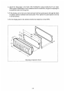
2.2 Processor Unit...........................................................................................................2-4
2.3 Transceiver Unit.........................................................................................................2-4
2.4 Junction Box..............................................................................................................2-4
2.5 Transducer (Hull Unit)................................................................................................2-5
2.6 Rate-of-Turn Gyro Unit (Option).................................................................................2-7
2.6.1 Mounting Procedure........................................................................................2-7
2.6.2 Leveling Adjustment ........................................................................................2-8
CHAPTER 3. WIRING ........................................................................................3-1
3.1 Precautions for Cable Installation...............................................................................3-1
3.1.1 Cable between hull Unit (transducer) and Transceiver ....................................3-1
3.1.2 Cable between transceiver Unit and Processor Unit (via Junction Box)...........3-1
3.1.3 Other Connection Cables of DS-30 .................................................................3-1
3.2 Cable Specification ....................................................................................................3-2
3.3 Cable Fabrication.......................................................................................................3-5
3.3.1 Transducer Cable............................................................................................3-5
3.3.2 Cables between Transceiver Unit/Junction Box/Processor Unit (TTYCY-16S).3-5
3.3.3 Cables between Processor Unit/Main Display Unit/Sub Display Unit
(CO-SPEVV-SB-C 0.2x10P)............................................................................3-6
3.3.4 CIF/NMEA Data Signal Cable (CO-SPEVV-SB-C 0.2x5P)...............................3-8
3.3.5 Other Cables...................................................................................................3-9
3.3.6 Insulation of cables for transducer.................................................................3-10
3.4 Remarks on Connection with Other Equipment........................................................ 3-11
3.4.1 KP Input Signal for Interference Rejection..................................................... 3-11
3.4.2 CIF/NMEA Signal I/O Circuit.......................................................................... 3-11
3.4.3 Requirement of Wind Direction and Speed Signal......................................... 3-11
3.4.4 Requirement in Engine Revolution Speed Signal........................................... 3-11
3.4.5 Connection of Gyro Signal (RS-232C)...........................................................3-12
CHAPTER 4. POST-INSTALLATION SETTING ................................................4-1
4.1 DIP Switch Setting .....................................................................................................4-1
4.1.1 Display Unit.....................................................................................................4-1
4.1.2 Processor Unit.................................................................................................4-2
4.1.3 Distribution Box...............................................................................................4-3
4.1.4 Digital Indicator DS-351 (option)......................................................................4-4
4.2 Setting Offset Data Menu...........................................................................................4-5
4.3 Setting System Menu.................................................................................................4-7
4.3.1 Opening System Menu....................................................................................4-7