


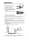
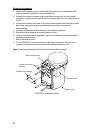

9
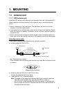
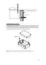
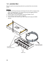
Flush mounting
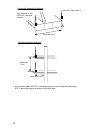
Optional flush mount kit A or B is required for flush mounting. For mounting
dimensions, refer to the outline drawing at the back of this manual.
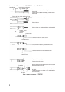
Flush mount kit A: Type OP24-1 Code no. 005-950-740
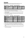
Name Type Code no. Qty
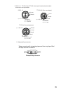
1 Cosmetic panel 24-003-2811 100-299-540 1
2 +Tapping screw 5x25 000-802-082 4
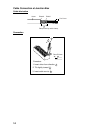
1. Cut out a hole in the mounting location, referring to the outline drawing.
2. Remove two hex bolts to dismount the mounting base.
3. Remove six hex bolts from the bottom of the transponder unit to dismount the
mounting pedestal.
4. Set the transponder unit to the cosmetic panel and fix them with six hex bolts.
5. Set the assembly (transponder unit and cosmetic panel) to the hole and fix it
with four tapping screws (5x25).
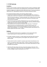
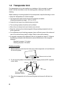
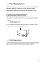
Flush mount kit B: Type OP24-2 Code no. 005-950-750
Name Type Code no. Qty
1 Mounting bracket 24-003-2821 100-299-550 1
2 Hex bolt M5x25 000-862-125 6
3 Hex nut M5 000-863-108 6
4 Flat washer M5 000-864-128 6
5 Spring washer M5 000-864-258 6
1. Cut out a hole in the mounting location, referring to the outline drawing.
2. Dismount the mounting base and mounting pedestal from the transponder unit.
3. Set the transponder unit to the hole. Using six hex bolts, attach the mounting
bracket at the bottom of the transponder unit from the rear of the flush mounting
panel.
4. Fix with six sets of hex bolt, nut, flat washers and spring washers from the rear
of the flush mounting panel.