


12
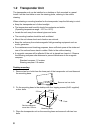
2. WIRING
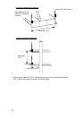
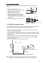
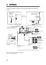
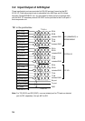
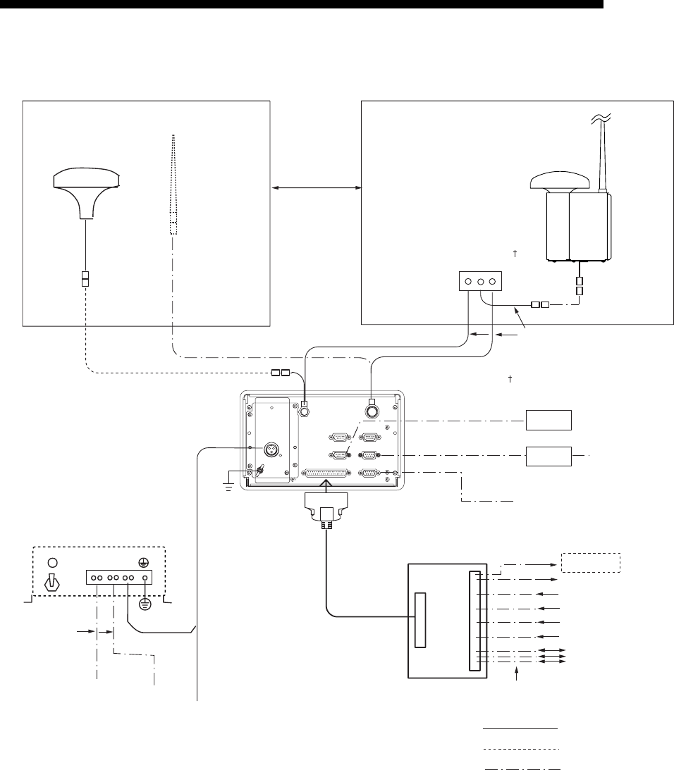
Connect the equipment, referring to the interconnection diagram at the back this
manual.
AD-10 IN
EXTRA I/O
GPS Antenna
GPA-017S
GSC-001
PC
AD-100
150M-W2VN
Either one
RG-10/UY
RG-10/UY
Attached to Distributor
(approx. 1m)
Gyrocompass
LAN cable
(category 4 or higher)
TTYCS-1Q**
AIS sentence out
(4800 bps)
Distributor unit
DB-1
Alarm out
GPS receiver
Heading sensor
Speed sensor or ROT
Beacon receiver
AIS data In/Out
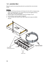
Junction Box
CB-100
AC
IN
DC
IN
DC
OUT
12-24 VDC
(Connect to the alternative
power source.)
*: If the ship’s mains is 12 VDC, cable length should be less than 50 cm.
Ship’s mains
100-115/200-230 VAC
1φ, 50/60 Hz
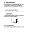
Power Supply
PR-240-CE
MJ-A3SPF0013-035 (3.5 m) *
Transponder
unit
FA-100
GPS/VHF Conbined
Antenna GVA-100
8D-FB-CV, 30 m/50 m: Option
RG-10/UY: Local supply
: Standard
: Option
: Local Supply
DPYC-1.5**
LAN
0.6 m
***
***
***
0.9 m
GPS ANT
VHF ANT
Approx. 3.3 m
TTYCS-1Q** or TTYCS-4**
24 VDC
: ground is not required.
1.5 sq
AUX-2
AUX-1
Pilot Plug
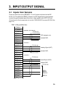
EXTRA IO port: Outputs AIS sentence (4800 bps).
AUX-1, AUX-2 port: Not used.