


2. RADAR, CHART RADAR OPERATION
2-42
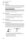
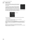
2.29 Interswitch
The interswitch uses a network to transfer multiple radar signals to the monitor units
connected in the network. A master/slave relation can be set for a single radar signal
and that signal can be shown on multiple displays. Up to four antennas and four dis-
play units can be connected. Set the radar display and antenna groups from the [An-
tenna] button on the Status bar.
When you switch to a different antenna, the heading skew and timing adjustment (set
at installation) for that antenna are automatically applied.
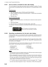
The [Antenna] button on the Status bar shows current antenna selection.
Note: Switch to a different antenna or change the interswitch settings in the standby
mode.
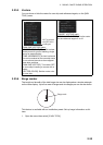
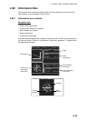
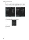
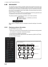
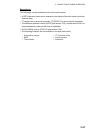
2.29.1 Displaying antenna information
The [ANT SELECT] menu shows:
• Radar band, output power and antenna position of each antenna currently powered.
(If an antenna is not powered, its data area is blank.)
• Current antenna and display combinations.
To show antenna information, open the menu then select the [8 INITIAL SETTING]
and [5 ANT SELECT] menus.
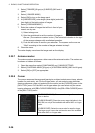
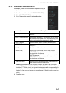
[Antenna] button
- ANT-3(M): Antenna no. 3, (M)=Master (or (S)=Slave)
- X-BAND (or S-BAND)
←
←
←
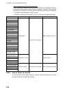
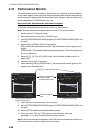
ANT 1 : X-BAND
25UP Main Top
ANT 2 : S-BAND
30UP Main 2nd
ANT 3 : X-BAND
12 Fore
ANT 4 : X-BAND
12 Aft
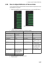
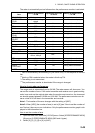
Using the information displayed in this example the antenna system configuration would
look something like this.
ANT1
ANT2
ANT3
ANT4
Antenna Unit
Power Supply Unit
Processor Unit
HUB-3000
DISP1 DISP2
DISP3 DISP4