


4
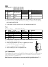
F type
Flush Mount Kit (F): OP02-79-1 (001-229-290)
OP02-79-2 (001-229-300)
OP02-79-3 (001-229-310)
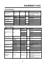
No. Name Type Code no. Qty Remarks
100-279-270 OP02-79-1:N3.0
100-279-280 OP02-79-2:2.5GY5/1.5
1
Cosmetic
panel
02-129-1041-0
100-279-290
1
OP02-79-3:7.5GY7/2
2 Hex bolt M6x12
000-162-897-1
0
4
3
Spring
washer
M6
000-158-855-1
0
4
1. Prepare a cutout in the mounting location whose dimensions are 210 (W) x 194 (H) mm.
2. Attach the cosmetic panel (02-129-1041-0) to the display unit with four hex bolts (M6x12)
and four spring washers (M6).
3. Fix the display unit to the mounting location with four tapping screws (5x20).
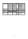
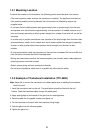
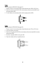
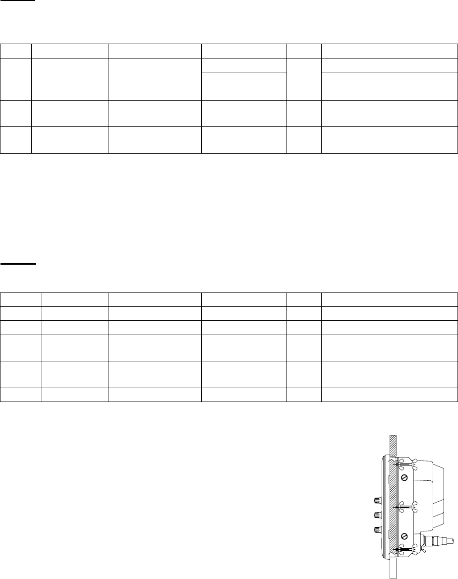
S type
Flush Mount Kit (S): OP02-80 (001-229-320)
No. Name Type Code no. Qty Remarks
1 Fixing plate 02-129-1045-0 100-279-300 2
2 Wing bolt M4x30 000-804-799 6
3 Hex bolt M6x12
000-162-897-1
0
4
4
Spring
washer
M6
000-158-855-1
0
4
5 Wing nut M4 000-863-306 6
1. Prepare a cutout in the mounting location whose dimensions are 194 x 194 mm.
2. Insert the display unit to the cutout.
3. Attach two fixing plates (02-129-1045-0) to the display unit with four
hex bolts (M6x12) and spring four washers (M6).
4. Screw six wing bolts (M4x30) to wing nuts (M4).
5. Fasten the display unit with six wing bolts and nuts.
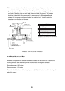
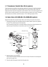
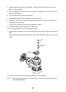
1.3 Transducer
The installation of the transducer and the tank should be accomplished by a dockyard referring
to the installation drawings at the back of this manual. An example of transducer installation
method is also shown in paragraph 1.3.2.
Note: Discussions should take place and agreement reached with the dockyard for sufficient
reinforcement and watertightness of the hull to comply with the regulations concerned.