


12
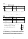
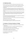
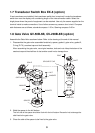
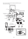
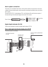
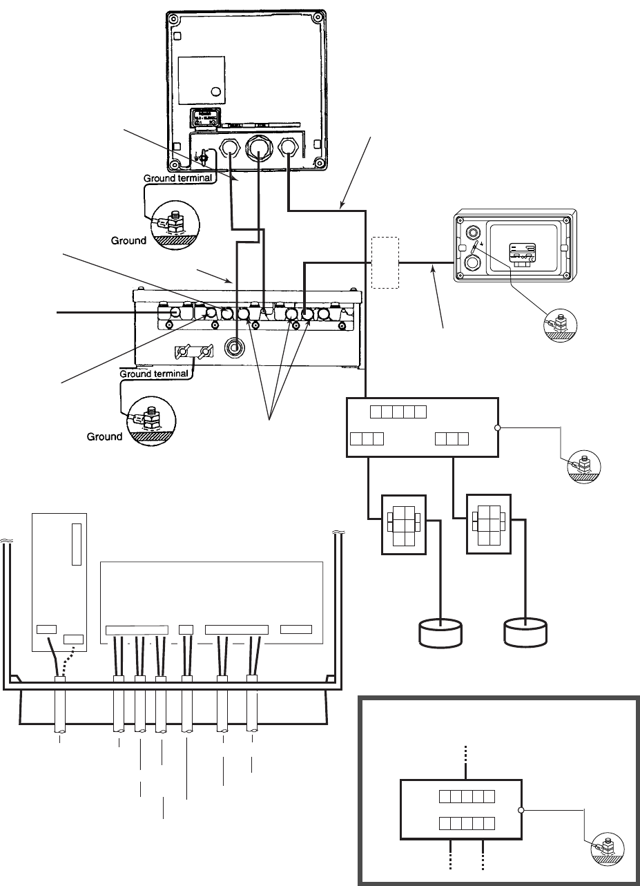
When the Transducer Switch Box EX-8 or Distribution Box MB-1200 is used, the
interconnections are as follows.
12345678910
12345678910
12
12345
TB1
TB2
TB3
TB4
123
123
AC
TB5
DC
TB6
TB7
1 2 3 4 5
TB3
1 2 3
TB1
FORE
1 2 3
TB2
AFT
1a
2a
3a
1T
2T
3T
TB1
TB2
2RNCT-SB
2CX2.5
1a
2a
3a
1T
2T
3T
TB1
TB2
2RNCT-SB
2CX2.5
2.0 sq
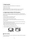
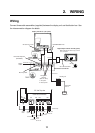
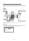
Display unit FE-701 (rear panel)
2.0 sq
MJ-A3SPF0015-100C
POWER
DATA
XDR
Ship's
mains
Alarm system
Personal computer
(EIA-232C)
DPYCYS-1.5
2.0 sq
Navigation
Device
(IEC 61162-1)
*1
*1
*2
*1: with power
*2: without power
TTYCYS-4
Distribution
box
FE-702
RECORDER
Ground
Digital depth indicator FE-720 (option)
When silencing the alarm beep, connect
to *2 connector.
1.25 sq
Terminal
Box
MJ-A7SPF0009-020C
TRANSDUCER SWITCH BOX *3
EX-8 (option)
Ground
Matching box
Matching box
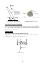
Transducer
FORE
Transducer
AFT
Cable clamp
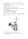
CONE board 02P6283
FE-702 Top view
Ship's
Main
FE-720FE-720
Power
Source
for FE-701
IEC
61162-1
PC
Alarm
System
TTYCYS-4
TTYCYS-4
TPYCYS-1.5
TTYCYS-4
FM-C6FPS003-020
MJ-A10SPF0002-100
*3: Connection of Distribution Box
MB-1200(option)
1 2 3 4 5
TB1
2.0 sq
GND
5 2 1 4 3
TB2
DISTRIBUTION BOX
MB-1200