


9
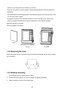
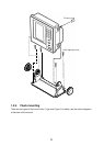
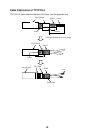
1.7 Transducer Switch Box EX-8 (option)
If two transducers are installed, the transducers switch box is required. Locate the transducer
switch box near the display unit considering length of the interconnection cable. Select the
bright place where the panel of equipment can be watched. Use only the screws supplied on the
terminal inside to make connections. Use of other screws may cause a short circuit. Compass
safe distances are as follows; standard compass: 1.00 m, Steering compass: 0.60 m.
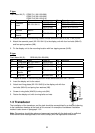
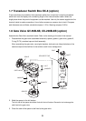
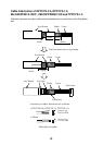
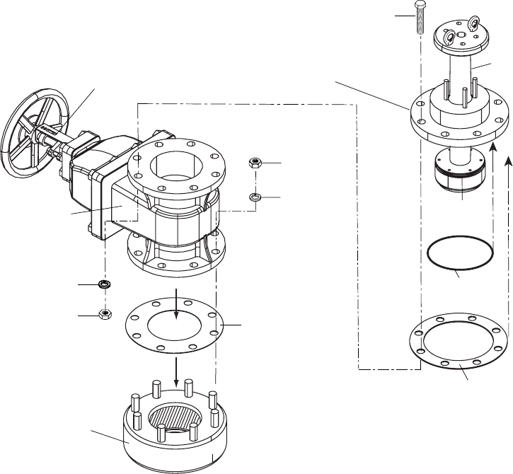
1.8 Gate Valve GV-50B-6B, GV-200B-8B (option)
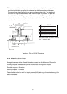
Assemble the Gate Valve as shown below. Refer to the drawing at the end of this manual.
1. Disassemble the gate valve assembled tentatively: spacer, gasket1, gate valve, gasket 2,
O-ring (P170), seachest cap and shaft assembly.
When assembling the gate valve, use original washers, bolts and nuts. Keep the bottom of the
seachest cap and the shaft free of dust and be careful not to damage them.
1
SPACER
GASKET1
NUT
WASHER
GATE VALVE
NUT
WASHER
BOLT
GASKET2
O-RING
(P170)
SEACHEST CAP
SHAFT
O-RING
(P135)
SCALE
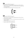
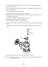
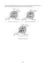
2. Weld the spacer to the hull bottom.
The hull side of the spacer should be flush with the hull bottom. Be careful not to damage the
side fixed to the gate valve.
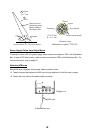
3. Clean the side of the spacer to be fixed to the gate valve.