


www.furuno.com
All brand and product names are trademarks, registered trademarks or service marks of their respective holders.
Installation Manual
Color Scanning Sonar
Model FSV-35/FSV-35S
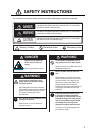
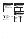
SAFETY INSTRUCTIONS ................................................................................................ i
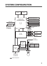
SYSTEM CONFIGURATION .......................................................................................... iii
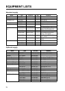
EQUIPMENT LISTS........................................................................................................ iv
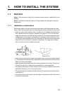
1. HOW TO INSTALL THE SYSTEM ..........................................................................1-1
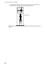
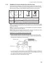
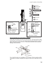
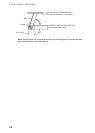
1.1 Hull Unit .............................................................................................................................1-1
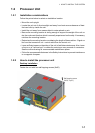
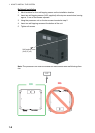
1.2 Processor Unit ...................................................................................................................1-7
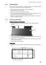
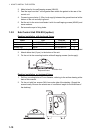
1.3 Control Unit........................................................................................................................1-9
1.4 Transceiver Unit...............................................................................................................1-11
1.5 Transducer Cable Extension Kit .....................................................................................1-12
1.6 IF Unit ..............................................................................................................................1-13
1.7 Grounding the Equipment................................................................................................1-13
1.8 Attachment Flange (option)..............................................................................................1-13
1.9 Attachment Kit (option) ....................................................................................................1-14
2. WIRING....................................................................................................................2-1
2.1 How to Use the Crimping Tool, Pin Extractor ....................................................................2-1
2.2 How to Connect Units ........................................................................................................2-2
2.3 Processor Unit ...................................................................................................................2-3
2.4 IF Unit ................................................................................................................................2-6
2.5 Control Unit and Remote Controller...................................................................................2-9
2.6 Transceiver Unit...............................................................................................................2-11
2.7 Transducer Cable Extension Kit .....................................................................................2-14
2.8 Control Box of Hull Unit....................................................................................................2-15
2.9 Input Voltage and Fuses..................................................................................................2-16
3. ADJUSTMENTS AND CHECKS .............................................................................3-1
3.1 Hull Unit Check ..................................................................................................................3-1
3.2 How to Adjust the Heading ................................................................................................3-3
3.3 How to Configure the Own Ship Mark................................................................................3-4
3.4 Others Menu ......................................................................................................................3-5
APPENDIX 1 JIS CABLE GUIDE .............................................................................AP-1
PACKING LISTS ......................................................................................................... A-1
OUTLINE DRAWINGS ................................................................................................ D-1
INTERCONNECTION DIAGRAM ................................................................................ S-1