


2. WIRING
2-13
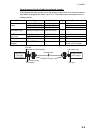
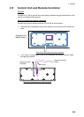
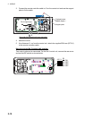
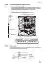
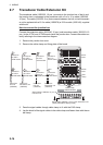
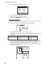
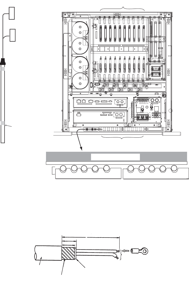
2.6.2 Connections inside the transceiver unit
1. Remove the transceiver unit cover.
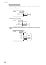
2. Connect transducer cable (cables from the transducer) referring to cable no. la-
beled on the chassis and connector no. labeled on each pc board. Connect the
XH connector of the cable from the transducer to the TRX board.
3. Arrange the cables in numerical order and fix them with the cable clamp.
4. Remove the metal fixing the transducer cable of the hull unit.
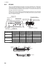
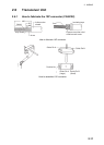
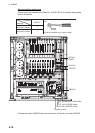
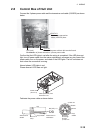
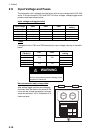
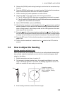
2.6.3 Power cable
Connect the power cable DPYCYS-2.5 (or the equivalent) to TB-101 of the transceiver
unit. Fabricate the power cable as shown below.
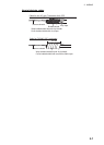
P1
(34 pin)
Fasten shield with
steel clamp.
10S2223 (10 pcs.)
Clamp for transducer cables
Cable
No.
13-L
16-L
05-L
SB-1909
SB-1909
07-L
SM4P
EL4P
SM12P
YL8P
EL3P
SM12PSM8P
EL12P EL9P
SM18P
VH-3P
EDS3
EDS3
EDS3
TB-B101
INPUT
F602
I
MAINTENANCE
Maintenance
I
F601
MAIN
J601
/220/230 VAC
50/60Hz
12
:15A
L
L
S605
L
L
S605
H
S603INPUT(TB-B101)
L100V
H110V
H
S603
S604
H
S604
L
H
H
L
H
L
H220V
L
H230V
HH115V L
(Should be OFF
operation.)
for Normal
Use Only.
100/110/115
15A15A
J303J302J301
5A5A
J206J205J204
J201 J202 J203
6962 6963
CN-B202 CN-B201CN-B203CN-B205CN-B206 CN-B204
CN-B208CN-B209CN-B210 CN-B207
TRX-2 TRX-1TRX-3TRX-5TRX-6 TRX-4
TRX-8TRX-9TRX-10 TRX-7
10 9 8 7 6 5 4 3 2 1
㪝㫉㫆㫄㩷㫋㪿㪼㩷㫉㫀㪾㪿㫋㪒㩷䌂㪉㪇㪈㸢㪙㪉㪇㪉㸢㪅㪅㪅㸢䌂㪉㪈㪇
P2
(34 pin)
Transceiver Unit
Vinyl sheath
Anti-corrosive
sheath
Crimp-on lug
FV2-4 (2 pcs.)
35
30
Set armor in cable clamp.
140
Dimensions in
millimeters