


1. HOW TO INSTALL THE SYSTEM
1-13
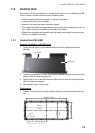
1.6 IF Unit
Refer to the outline drawing at the back of this manual for mounting dimensions. Fas-
ten the unit with 5x20 self-tapping screws. If the unit is to be installed on a bulkhead,
be sure that the location does not allow water to drip into the cable entrance.
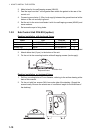
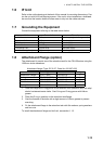
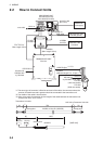
1.7 Grounding the Equipment
Ground the equipment referring to the table shown below.
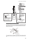
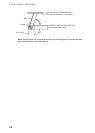
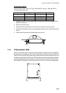
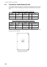
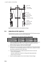
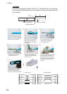
1.8 Attachment Flange (option)
The attachment kit permits use of the retraction tank for the CSH-20 series using the
1200 mm stroke transducer.
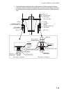
Attachment flange (Type: OP10-27. Code No. 000-067-050)
1. Clean the flange and O-ring groove of the retraction tank (welded to hull) with ethyl
alcohol moistened waste cloths. Coat O-ring and O-ring groove with lithium
grease.
2. Place the O-ring in position on the retraction tank flange.
3. Coat the threads of the bolts with a slight amount of lithium grease to prevent
scorching.
4. Fix the attachment flange to the retraction tank with flat washers, spring washers
and hex nuts.
To install the attachment flange and hull unit, see section 1.1.3.
Unit Ground wire Remarks
Hull Unit IV-8sq Local supply (protective ground)
Processor Unit IV-8sq Local supply
IF Unit IV-2sq Local supply
Control Unit IV-1.25sq Local supply
Transceiver Unit Copper strap Standard supply
Junction Box (option) Copper strap Local supply
Name Type Code No. Qty
Attachment Flange 10-077-5802 100-303-610 1
O-ring CO 0318A(V585) 000-166-370-10 1
Hex. Nut M20 SUS304 000-863-116 48
Flat Washer M20 SUS304 000-864-136 24
Spring Washer M20 SUS304 000-864-270 24