


1. INSTALLATION
1-17
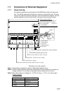
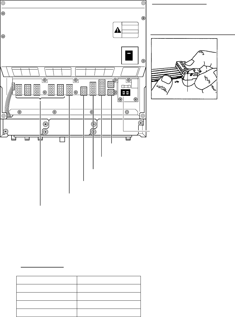
1.7 Connection of External Equipment
1.7.1 General wiring
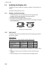
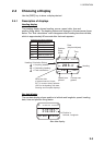
All external equipment are terminated on the MAIN Board inside the processor
unit. Turn off the power and unfasten four screws to remove the cover. Connect
wiring from external equipment referring to the interconnection diagram. Use the
opener supplied to open terminal blocks, referring to the instructions below.
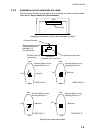
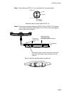
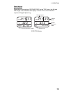
From top: Analog Roll, Analog Pitch, 2-pole. See Note.
LOG/ALARM (Contact signal, 6-pole)
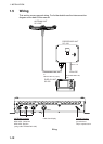
Recommended Cables*:
Power cable: DPYC-1.5
IEC 61162 equipment: TTYCS-1
AD-10 equipment: TTYCS-1Q
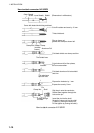
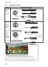
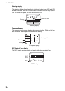
1. Insert opener.
2. Press opener.
3. Insert core.
4. Release opener.
Opener
How to insert cores in terminal blocks
DATA IN (AD-10/IEC 61162-1/2, 5-pole)
BEACON EXT (RTCM SC-104, 3-pole)
DATA OUT6 (AD-10, 4-pole)
DATA OUT1-DATA OUT5 (AD-10/IEC 61162-1/2, 4-pole)
Power Cable
* Or equivalent
Processor unit, cover opened
Note 1: Attach labels (supplied) to cables to differentiate between them.
Note 2: A plastic sheet is placed across the cable glands of the processor unit to keep out
foreign material. Cut out holes in the plastic where cables are to be lead in.
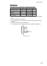
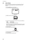
Note 3: Roll, pitch analog out voltage [V] = 0.0785 x θ (deg.) + 3.5 (θ = roll, pitch angle)
Output example
Roll or pitch angle Analog out voltage
0 [deg] 3.5 [V]
5 [deg] 3.8925 [V]
10 [deg] 4.285 [V]
20 [deg] 5.07 [V]