


2. INSTALLATION
2-16
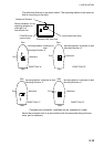
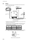
2.5 Wiring
This section covers general wiring. For further details see the interconnection
diagram at the back of this manual.
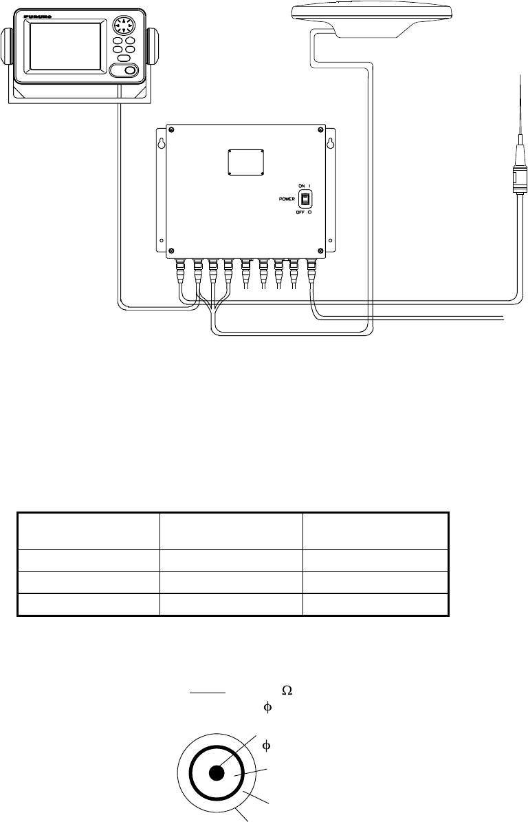
DISPLAY UNIT
SC-602
PROCESSOR UNIT
SC-601/SC-601-D
DGPS
ANTENNA
GR-800-1-S
*
12-24 VDC
ANTENNA UNIT
SC-303
MJ-A7SPF0006-100,
10m
TPPX6-3D2V-15M, 15m
TNC-PS-3D (15 m)
MJ-A3SPF0013-035,
3.5 m
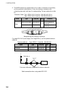
General wiring diagram
•
The display cable (display and processor units) is 10 m long. Connect it to the
DISPLAY port on the processor unit.
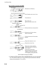
•
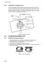
The antenna cable is 15 meters (standard length). Connect the three coaxial
cables to the processor unit according to cable color as below. Incorrect
connection will result in wrong heading.
Antenna TPPX6-3D2V-15M
Port on
Processor Unit
Antenna Element 1 No color GPS ANT 1
Antenna Element 2 Yellow GPS ANT 2
Antenna Element 3 Red GPS ANT 3
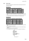
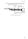
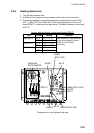
Note 1: Instead of TPPX6-3D2V, three Japan Industrial Standard coaxial cables
3D2V (local supply) or equivalent can be used as antenna cables.
Core
0.96 mm
Sheath
Shield
Insulator T1.02 mm
3D2V
50
5.3 mm
Sectional view of coaxial cable 3D2V