


GTX 330 Installation Manual Page 2-7
190-00207-02 Revision G
2.8.2 Mechanical Installation
NOTE
Avoid installing the unit near heat sources. If this is not possible, insure
that additional cooling is provided. Allow adequate space for installation
of cables and connectors. The installer will supply and fabricate all of
the cables. All wiring must be in accordance with FAA AC 43.13-1B
and AC 43.13-2A.
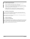
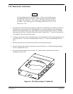
1. Assemble the connector/rack kit according to Figure B-2. Install the rack assembly according to
the dimensions given in Figure B-1 and paragraph 1.6.2, Physical Characteristics. Mounting
brackets are not supplied due to the wide range of mounting configurations available. Suitable
mounting brackets may be fabricated from sheet metal or angle stock. To insure a sturdy mount,
rear support for the unit must be provided.
2. Looking at the bottom of the transponder, make sure the front lobe of the locking mechanism is in
a vertical position. This can be accomplished by using a 3/32” Allen wrench through the face
plate.
3. Slide the unit into the rack until the front lobe of the unit touches the rack.
4. Turn the Allen wrench clockwise until unit is secured in the rack. Continue turning until tight.
Do not overtighten the screw.
5. To remove the unit from the rack, turn the 3/32” Allen wrench counterclockwise until it
disengages from the rack.
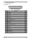
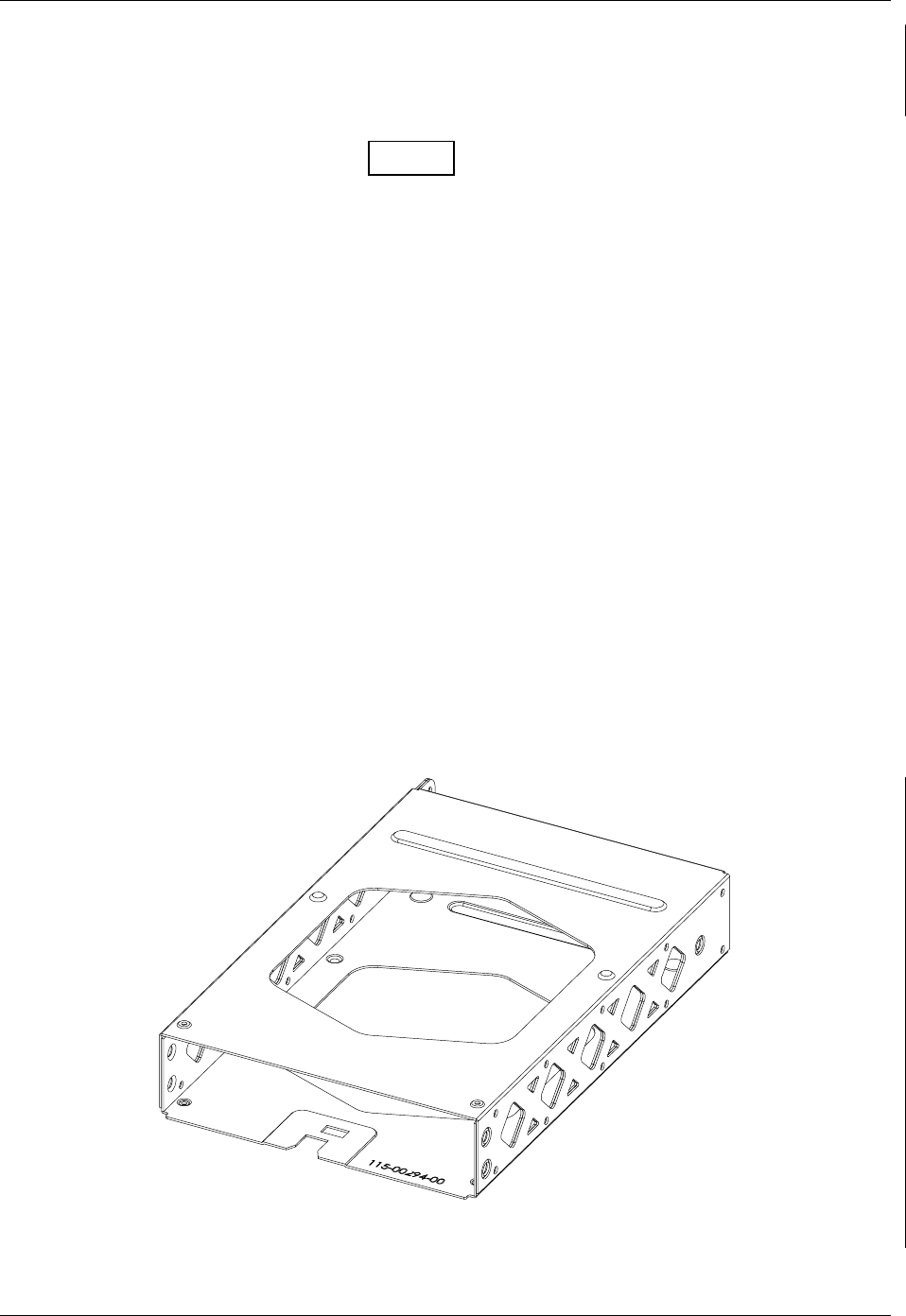
Figure 2-2. GTX 330 Unit Rack (115-00294-00)