


Page 4-10 GTX 330 Installation Manual
Revision G 190-00207-02
Refer to Section 5 for configuration. Configure ARINC 429 output CHANNEL 1 for GARMIN W/TIS
and ARINC 429 output CHANNEL 2 for GARMIN. TIS is then enabled over CHANNEL 1 when the
GTX 330 is connected to a Garmin 400/500 Series unit through the ARINC 429 wiring.
All configured input data that is concentrated through the GTX 330 via ARINC 429 lines, is received in
the second 400/500 Series unit via ARINC 429 CHANNEL 2 while the GTX 330 is active. No data is
received over ARINC 429 CHANNEL 2 while the GTX 330 is in remote standby. (Remote standby is
usually used as part of a dual transponder installation.)
4.6.4 ARINC 429 Input/Output
The ARINC 429 Output 2 port, J3301 pins 30 and 28, is at a high-impedance when in remote standby,
therefore not active. When two GTX 330s are installed, the two ARINC 429 Output 2 ports may be hard
wired together since the EXTERNAL STANDBY SELECT input is active for only one of the two
GTX 330s at any given time.
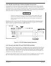
The GTX 330 ARINC 429 Output 1 port is active when J3301 pin 13 is grounded [EXTERNAL
STANDBY SELECT (remote STANDBY)]. In installations having a transponder combination of
GTX 330/GTX 327 (or GTX 330/other transponder), the GARMIN and GARMIN W/TIS formats from
the ARINC 429 Output 1 port, J3301 pins 34 and 37, are available if the GTX 330 has SW 3.03 and
above.
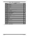
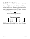
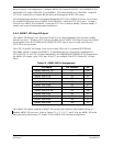
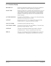
Table 4-9. ARINC 429 Pin Assignments
Pin Name Pin Number I/O
ARINC 429 OUT 1A 37 Out
ARINC 429 OUT 1B 34 Out
ARINC 429 IN 1A 32 In
ARINC 429 IN 1B 35 In
ARINC 429 IN 2A 33 In
ARINC 429 IN 2B 36 In
ARINC 429 OUT 2A 30 Out
ARINC 429 OUT 2B 28 Out
ARINC 429 IN 3A 26 In
ARINC 429 IN 3B 29 In
ARINC 429 IN 4A 48 In
ARINC 429 IN 4B 49 In
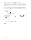
The ARINC 429 outputs conform to ARINC 429 electrical specifications when loaded with up to 5
standard ARINC 429 receivers. Refer to Figures C-1, C-3, C-5, C-7 and C-8 for the ARINC 429 serial
data interconnect and Sections 5.2.8 and 5.2.18 for ARINC 429 serial data configuration.