


GTX 330 Installation Manual Page 4-3
190-00207-02 Revision G
4.2 Power and Lighting Function
Power Input requirements and Lighting Bus input are listed in the following tables. The power-input pins
accept 11-33 Vdc. AIRCRAFT POWER 2 is for connecting to an alternate power source, such as on
aircraft with two electrical buses. Switched Power Out is a power source available for devices such as a
remote digital altitude encoder. Refer to Figure C-1 for power and lighting interconnections.
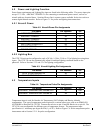
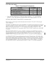
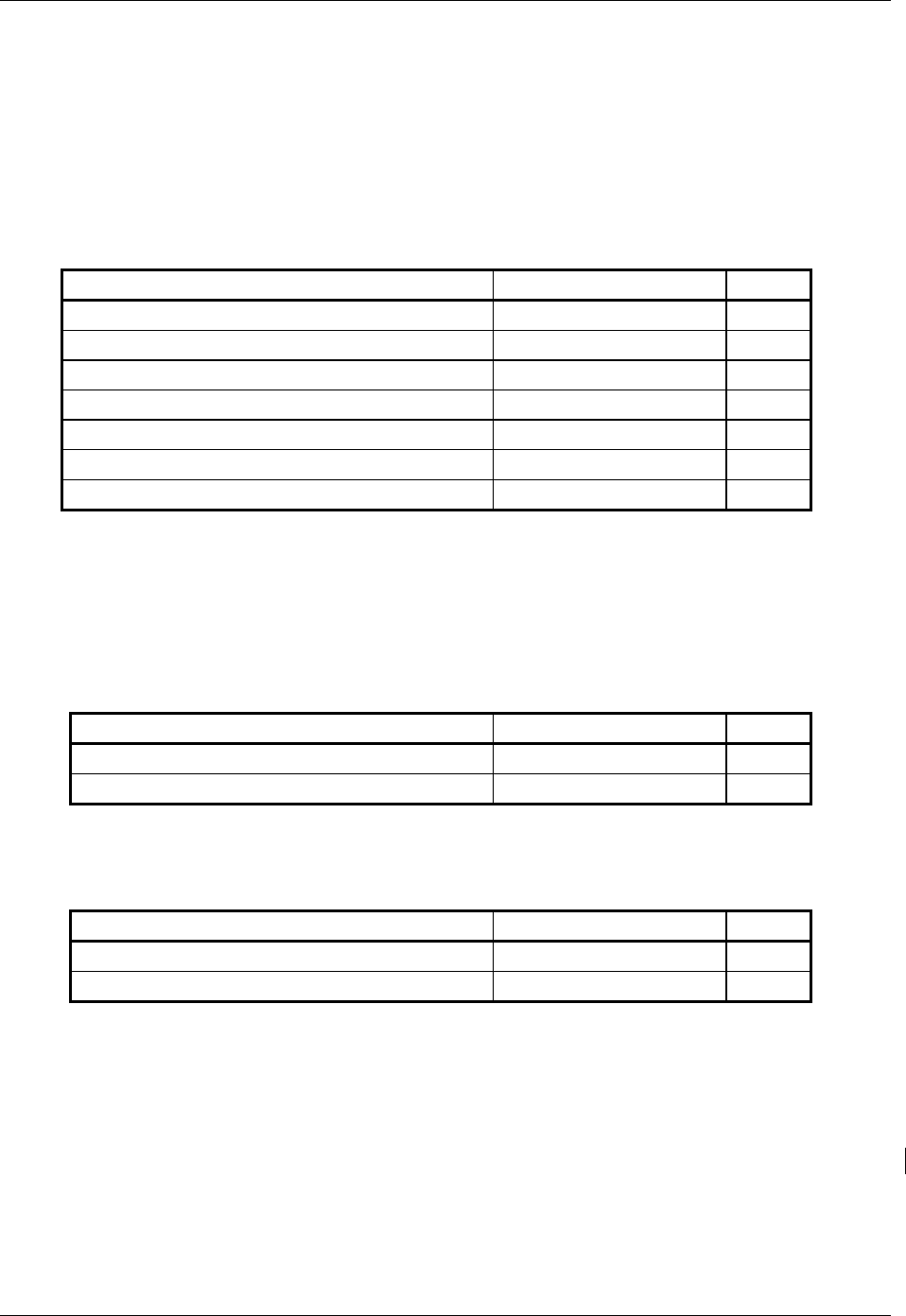
4.2.1 Aircraft Power
Table 4-2. Aircraft Power Pin Assignments
Pin Name Pin Number I/O
AIRCRAFT POWER 1 21 In
AIRCRAFT POWER 1 42 In
AIRCRAFT POWER 2 56 In
AIRCRAFT POWER 2 60 In
SWITCHED POWER OUT 62 Out
POWER GROUND 27 --
POWER GROUND 43 --
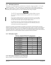
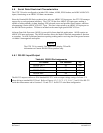
4.2.2 Lighting Bus
The GTX 330 unit can be configured to track a 28 Vdc, 14 Vdc, 5 Vdc or 5 Vac lighting bus using these
inputs. The GTX 330 can also automatically adjust for ambient lighting conditions based on the
photocell. Refer to Sections 5.2.5 and 5.2.6 for lighting configuration.
Table 4-3. Aircraft Lighting Pin Assignments
Pin Name Pin Number I/O
14 V/5 V LIGHTING BUS HI 45 In
28 V LIGHTING BUS HI 14 In
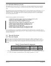
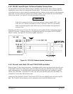
4.3 Temperature Inputs
Table 4-4. Temperature Probe Pin Assignments
Pin Name Pin Number I/O
CURRENT TEMPERATURE PROBE OUT 41 Out
CURRENT TEMPERATURE PROBE IN 44 In
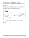
Temperature input is used for Outside Air Temperature (OAT) display and Density Altitude
computations. The type of temperature probe required is a current sensor type, such as an EDMO P/N
655-PROBE or Davtron P/N C307PS. Connect the red wire to pin 41 and the black wire to pin 44. The
GTX 330 is not configurable for different types of temperature sensors. The temperature-input
specification is 1 microamp per degree Kelvin (1 µA/
°K). Refer to Figure C-6 for the temperature probe
interconnect and to Section 5.2.11 for probe configuration.