


GTX 330 Installation Manual Page 4-9
190-00207-02 Revision G
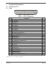
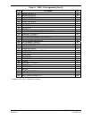
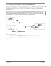
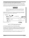
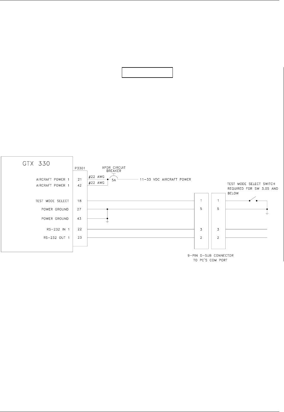
4.6.2 RS-232 Input/Output, Software Update Connections
An optional RS-232 serial data connector may be installed in the aircraft for future software upgrades,
negating the need to remove the transponder from the panel. The connector can be mounted anywhere
convenient for access, such as under the instrument panel, on a remote avionics shelf or in the instrument
panel itself. Be sure to label the connector for Software Update. Do not include the Test Mode Select
switch in the aircraft. See Figure 4-3 for software update connections.
CAUTION
If the unit is removed from the aircraft and operated, always connect J3302, (and
J3303 for GTX 330D) to an antenna or a 50 , 5-watt load. The GTX 330 transmits
Mode S acquisition squitter replies about once per second whether interrogations are
received or not.
Beginning with SW version 3.06, the GTX 330 software can be updated in the Configuration mode as
well as in Test mode. Updating software in Configuration mode does not require the TEST MODE
SELECT switch. See Figure 4-3 for software update connections.
Figure 4-3. GTX 330, Software Update Connections
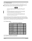
4.6.3 Aircraft with Both TIS and TCAS/TCAD Installed
Refer to Figure C-8 for wiring connections. If redundant traffic systems are desired in the aircraft, such
as TIS and TCAD/TCAS, both systems cannot be connected to the same 400/500 Series unit to display
traffic simultaneously. In a multiple traffic system/multiple 400/500 Series unit installation, connect
ARINC 429 CHANNEL 1 from the GTX 330 to only one of the 400/500 Series units and ARINC 429
CHANNEL 2 to the other 400/500 Series unit.
Connect the TIS CONNECT SELECT line from the GTX 330 to the 400/500 Series unit receiving TIS
data. The TCAD/TCAS system may now be connected to the second 400/500 Series unit.