


GPSMAP 6000/7000 Series Installation Instructions 13
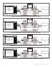
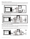
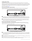
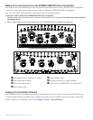
Advanced NMEA 0183 Wiring
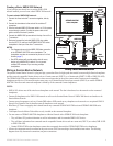
The GPSMAP 6000/7000 series chartplotter has four ports to receive NMEA 0183 data (RX ports), and two ports to send NMEA 0183 data
(TX ports). Wire one NMEA 0183 device per RX port to send data to a 6000/7000 series chartplotter, wire up to three NMEA 0183 devices in
parallel to each TX port to receive data from a 6000/7000 series chartplotter.
Each RX and TX port has 2 wires, labeled A (+) and B (-) according to the NMEA 0183 convention. Connect the corresponding A (+) and B (-)
wires of each port to the A (+) and B (-) wires of your NMEA 0183-compliant device. Refer to the table and wiring diagrams when wiring the
6000/7000 chartplotter to NMEA 0183 devices.
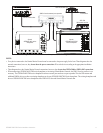
Consult the installation instructions for
your NMEA 0183-compliant device to identify the Transfer (TX) A (+) and B (-) wires and
Receiving (RX) A (+) and B (-) wires. Use 28 AWG, shielded, twisted-pair wiring for extended runs of wire. Solder all connections and seal
them with heat-shrink tubing.
Notes:
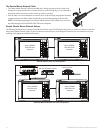
For two-way communication with a NMEA 0183 device, the ports on the GPSMAP 6000/7000 chartplotters are not linked. For example,
if the RX port of the NMEA-compliant device is wired to TX port 1 on the GPSMAP 6000/7000, you can wire the TX port of your NMEA
0183-compliant device to RX port 1, port 2, port 3, or port 4 on the GPSMAP 6000/7000.
The ground wires on the NMEA 0183 data cable from the GPSMAP 6000/7000 series chartplotter and your NMEA 0183-compliant device
must both be grounded.
Approved NMEA 0183 sentences—GPAPB, GPBOD, GPBWC, GPGGA, GPGLL, GPGSA, GPGSV, GPRMB, GPRMC, GPRTE, GPVTG,
GPWPL, GPXTE, and Garmin proprietary sentence
s—PGRME, PGRMM, and PGRMZ.
The GPSMAP 6000/7000 series chartplotter also includes support for the WPL sentence, DSC, and sonar NMEA 0183 input with support for
the DPT (depth) or DBT, MTW (water temperature), and VHW (water temperature, speed, and heading) sentences.
Select Congure > Communications on the GPSMAP 6000/7000 series chartplotter to set up NMEA 0183 communications. See the
GPSMAP 6000/7000 Series Owner’s Manual for details.
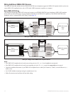
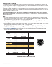
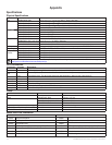
Port Wire Function Wire Color Pin Number Connector
Receiving
Port 1
RX / A (+)
White
1
RX / B (-)
Orange/White
2
Receiving
Port 2
RX / A (+)
Brown
5
RX / B (-)
Brown/White
6
Receiving
Port 3
RX / A (+)
Violet
9
RX / B (-)
Violet/White
10
Receiving
Port 4
RX / A (+)
Black/White
11
RX / B (-)
Red/White
12
Transmitting
Port 1
TX / A (+)
Gray
3
TX / B (-)
Pink
4
Transmitting
Port 2
TX / A (+)
Blue
7
TX / B (-)
Blue/White
8
N/A GPS 17
IN
Green/White
13
N/A GPS 17 OUT
Green
14
N/A SPARE 15
N/A A
LARM
Yellow
16
N/A A
CCESSORY ON
Orange
17
N/A G
ROUND
Black
18
N/A SPARE 19
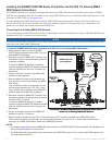
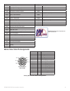
GPSMAP 6000/7000 Series NMEA 0183 Data Cable
•
•
•
•
•
NMEA 0183 Cable
End View
PIN 1
PIN 3
PIN 8
PIN 17
NMEA 0183 Cable
End View
PIN 1
PIN 3
PIN 8
PIN 17