


GPSMAP 6000/7000 Series Installation Instructions 7
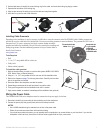
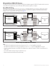
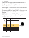
2. Use the table above to identify the correct locking ring for the cable, and locate the locking ring bag by number.
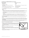
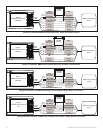
3. Separate the two halves of the locking ring.
4. Align the two halves of the locking ring over the cable and snap them together.
5. InserttheO-ringintotheendoftheconnector.
Installing a Locking Ring
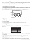
Installing Cable Grommets
Depending on the installation, it may be necessary to drill holes to route the connector end of the GPSMAP cables. Rubber grommets are
provided to cover the cable holes for a nished look. You may not need the grommets in some installations. The grommets do NOT create a
waterproof seal. To create a waterproof seal, apply a marine sealant around the
grommet and cable after installation. Be sure to test the system before installing and
sealing the grommets. Purchase additional grommets from your Garmin dealer or
directly from Garmin at
www.garmin.com.
Tools Required
Drill
1
1
/
4
in. (31.7 mm) paddle drill bit or hole saw
Utility knife
Marine sealant (optional)
To install the cable grommet:
1. Mark the location where you want to route the cable (power, NMEA 0183, NMEA
2000, Marine Video, or Marine Network.)
2. Using a 1
1
/
4
in. (31.7 mm) paddle drill bit or hole saw, drill the installation hole.
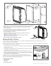
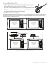
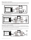
3. Refer to the diagram on page 7 for trimming instructions. Carefully trim the cable
hole in the grommet, as needed.
4. Route the cable to the chartplotter, and test the system.
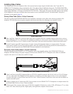
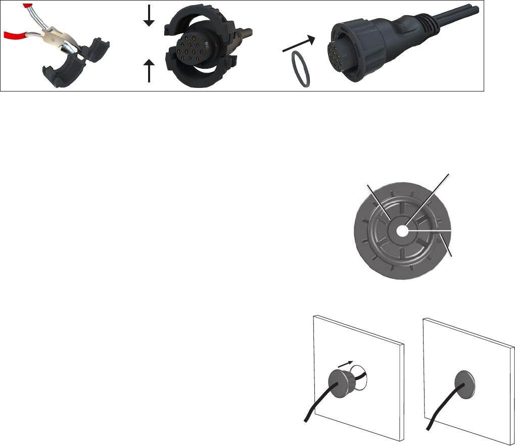
5. Spread the grommet apart at the split and place it around the cable.
6. Firmly push the grommet into the installation hole until it is seated.
7. Apply marine sealant, as needed, to weatherproof the installation-hole (optional).
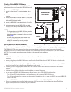
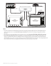
Wiring the Power Cable
The GPSMAP 6000/7000 series chartplotter must be connected to the power supply for the boat.
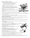
1. Route the included 2-pin power cable to the boat battery and to the chartplotter.
2. Connect the power (red) and ground (black) wires to the battery terminals.
NOTES:
Use 14 AWG shielded wiring for extended runs of wire to the power cable.
Solder all connections and seal them with heat-shrink tubing.
Ifyourboathasanelectricalsystem,youcanpossiblywirethechartplottertoanunusedholderonyourfuseblock.Ifyouwirethe
chartplotter to the fuse block, remove the in-line fuse holder supplied with the 2-pin power cable.
•
•
•
•
•
•
•
Trim to this line for the
Marine Video cable.
Use this hole (no
trim) for a power,
NMEA
0183,
Marine Network, or
NMEA 2000 cable
Split
Trim to this line for the
Marine Video cable.
Use this hole (no
trim) for a power,
NMEA
0183,
Marine Network, or
NMEA 2000 cable
Split