


GPSMAP 6000/7000 Series Installation Instructions 15
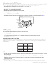
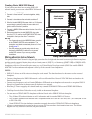
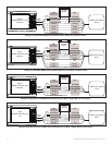
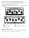
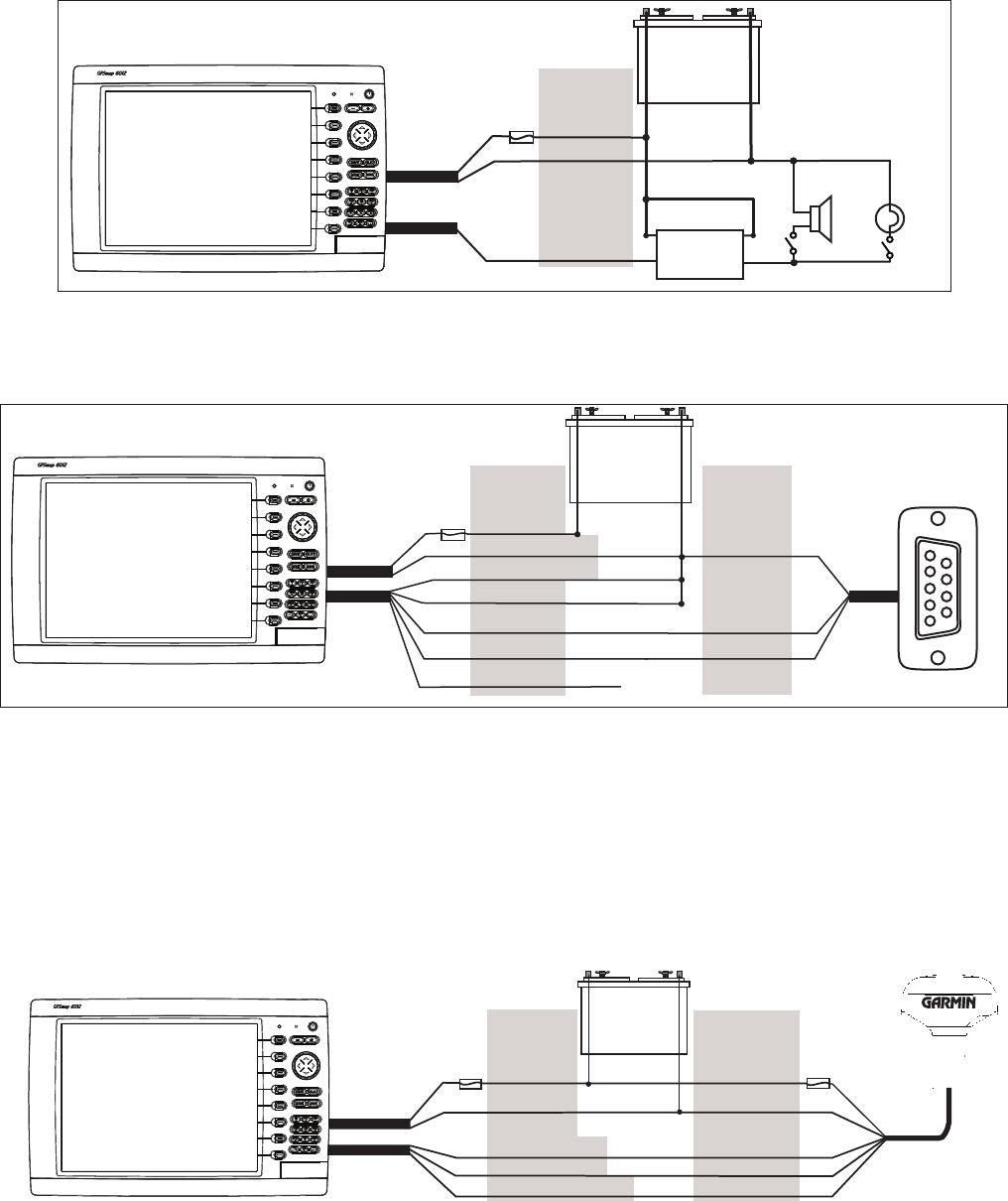
Wiring to a Lamp or to a Horn (Optional)
The GPSMAP 6000/7000 series chartplotter can be used with a lamp, a horn, or both, to sound or ash an alert when the chartplotter displays a
message. The alarm does not need to be wired for the GPSMAP 6000/7000 chartplotter to function. The alarm circuit switches to a low-voltage
state when the alarm sounds. The maximum current is 100 mA, and a relay is needed to limit the current from the chartplotter to 100 mA. To
manually toggle visual and audible alerts, install single-pole, single-throw switches.
Wiring to a Lamp, a Horn, or Both
+
-
Garmin
GPSMAP 6000/7000 series
chartplotter
WIRE
COLOR
RED (POWER)
BLACK (GND)
YELLOW (ALARM)
BATTERY
10–35
Vdc
R
ELAY
100 mA MAX
COIL CURRENT
HORN
LAMP
FUSE
7.5 A - 42 V
POWER
CABLE
NMEA 0183
C
ABLE
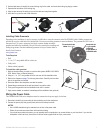
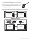
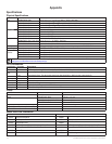
Wiring to a DB-9 PC Serial Connector
The GPSMAP 6000/7000 series chartplotters can be connected to a PC with a serial port by wiring the chartplotter to a DB-9 serial connector.
Wiring to a DB-9 Serial PC Connector
+
-
>
>
>
>
>
>
1
4
6
7
8
9
2
3
5
Garmin
GPSMAP 6000/7000 series
chartplotter
DB-9 serial
PC connector
BATTERY
10–35 Vdc
W
IRE
SEE TABLE FOR
WIRE COLORS
DB-9 PIN
NUMBERS
RED (POWER)
BLACK (PWR GND)
FUSE
7.5 A - 42 V
BLACK (DATA GND)
RX / B(-)
RX / A(+)
PIN
5: GND
PIN 3: TX
POWER
CABLE
NMEA 0183
C
ABLE
UNCONNECTED
PIN 2: RX
TX / B(-)
TX / A(+)
End View
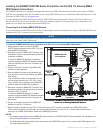
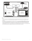
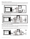
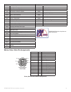
Wiring to a GPS 17 or GPS 17 HVS Antenna
If you already have a Garmin GPS 17 or GPS 17 HVS installed on your boat, you can wire it to the GPSMAP 6000/7000 series chartplotter
instead of installing the included GPS 17x. Wire the existing GPS 17 or GPS 17 HVS antenna to the included 19-pin NMEA 0183 cable as well
as to the power supply for the boat, referring to the diagram below. Use 22 AWG shielded wiring for extended runs of wire to the NMEA 0183
cable or GPS 17 HVS cable. Solder all connections and seal them with heat-shrink tubing.
NOTE: If you are using more than one Garmin chartplotter over a Garmin Marine Network, do not wire more than one chartplotter to a GPS
antenna. The GPS signal is shared between multiple chartplotters connected to a Garmin Marine Network.
Wiring to a GPS 17 or GPS 17 HVS Antenna
+
-
>
>
>
>
BATTERY
10–35 Vdc
W
IRE
COLOR
WIRE
COLOR
RED (POWER)
BLACK (GND)
ORANGE (ACC. ON)
GREEN (DATA OUT)
GREEN/WHITE (DATA IN)
RED (POWER)
BLACK (GND)
YELLOW (ON)
BLUE (DATA IN)
WHITE (DATA OUT)
FUSE
7.5 A - 42 V
FUSE
1 A
Garmin
GPSMAP 6000/7000 series
chartplotter
GPS 17 or
GPS
17 HVS
antenna
POWER
CABLE
NMEA 0183
C
ABLE