


GPSMAP 6000/7000 Series Installation Instructions 3
Flush Mounting the GPSMAP 6000/7000 Series Chartplotter
Hardware (included):
• Flush-mount template
• Rubber gasket
• Fourush-mountnut-plates
• Four 60 mm M3 × 0.5 screws (to secure the nut plate to the
mounting surface)
• Four M4 × 0.7 screws (to secure the chartplotter to the nut plate)
• Four 7 mm nylon washers (for the M4 × 0.7 screws)
Tools required (not included):
• Jigsaw
• Scissors
• Drill
• Drill bits—
3
/
8
in. (9.5 mm),
9
/
32
in. (7.2 mm), and
9
/
64
in. (3.5 mm)
• Number 2 Phillips screwdriver
• Center punch and hammer
• File and sandpaper
1. Theush-mounttemplateisincludedintheproductbox.Trimthetemplateandensurethatitwilltinthelocationatwhichyouwanttoush
mount the chartplotter.
NOTES:
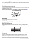
Ensure that the surface on which you mount the chartplotter has enough open space behind it to accommodate the chartplotter and the
connectedwires.Refertothediagramontheush-mounttemplatefortheclearance-spaceneededbyyourchartplotter.
Ensure that there is at least
1
/
2
in. (13 mm) of space on the right side of the chartplotter to access the SD card door, as indicated on the
ush-mounttemplate.
Ensurethatenoughventilationispresentbehindthemountingsurfacetocreatesufcientairowtopreventthechartplotterfrom
overheating.
To avoid interference, mount GPSMAP 6008/6208 chartplotters 15 in. (38.1 cm), GPSMAP 6012/6212 chartplotters 16 in. (40.6 cm),
GPSMAP 7012/7212 chartplotters 25 in. (63.5 cm) and 7015/7215 chartplotters 17 in. (43.2 cm) from a magnetic compass.
2. Theush-mounttemplatehasadhesiveontheback.Removetheprotectivelinerandapplythetemplatetothelocationatwhichyouwantto
ushmountthechartplotter.
3. Using a
3
/
8
in. (9.5 mm) drill bit, drill one or more of the four pilot holes inside the corner of the template to begin cutting the mounting
surface.
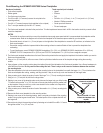
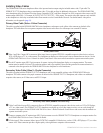
4. Usingajigsaw,cutthemountingsurfacealongtheinsideofthesolidlineindicatedontheush-mounttemplate.Usealeandsandpaperto
renethesizeofthehole.Be very careful when cutting this hole. There is only a small amount of clearance between the case and
the mounting holes.
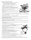
5. Place the chartplotter in the hole and ensure that the mounting holes on the chartplotter line up with the larger
9
/
32
in. (7.2 mm) holes on the
ush-mounttemplateaftercutting,sanding,andlingthehole.Iftheydonotlineup,marknewlocationsforthelargerholes.
6. Using a center punch, indent the center of each of the larger
9
/
32
in. (7.2 mm) mounting-hole locations.
7. Using a
9
/
32
in. (7.2 mm) drill bit, drill the four larger holes.
8. Starting in one corner of the template, place a nut plate over the larger hole you drilled in step
7. Ensure that the smaller
9
/
64
in. (3.5 mm) hole on the nut plate lines up with the smaller hole
onthetemplate.Iftheydonotlineup,markanewlocationforthesmallerhole.Repeatthis
step for each corner of the template.
9. Using a center punch, indent the center of each of the smaller
9
/
64
in. (3.5 mm) mounting-hole
locations.
10.Removetheush-mounttemplatefromthemountingsurface.
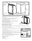
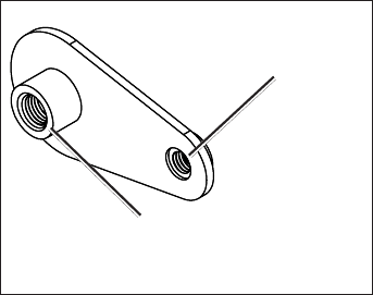
11. Starting in one corner of the mounting location, place a nut plate on the back of the mounting
surface,liningupthelargeandsmallholes.Theraisedportionofthenutplateshouldtinto
the larger hole.
12. Secure the nut plate to the mounting surface by fastening an included 60 mm M3 × 0.5 screw
through the smaller
9
/
64
in. (3.5 mm) hole.
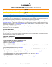
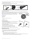
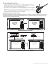
•
•
•
•
Use the 60 mm M3 × 0.5 screw
to fasten the nut plate to the
mounting surface
Use the 70 mm M4 × 0.7 screw
to fasten the chartplotter to the
nut plate
Flush-mount Nut Plate
Use the 60 mm M3 × 0.5 screw
to fasten the nut plate to the
mounting surface
Use the 70 mm M4 × 0.7 screw
to fasten the chartplotter to the
nut plate
Flush-mount Nut Plate