


12 308647
Service
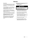
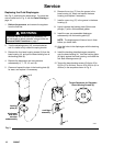
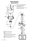
Replacing the Fluid Diaphragms
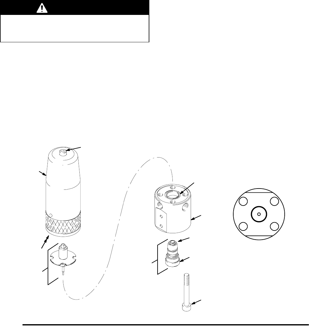
See Fig. 3, and follow the steps below. For parts that
are not called out in Fig. 3, see the Parts Drawing on
page 14.
1. Relieve the pressure, and remove the regulator
from the fluid line.
WARNING
To reduce the risk of serious injury whenever you
are instructed to relieve pressure, always follow the
Pressure Relief Procedure on page 7.
2. Turn the adjusting screw (10) counterclockwise
until it is loose to fully relieve the spring tension.
3. Remove the four base housing screws (9) from the
base housing (4), and pull the base housing free of
the backing plate (8).
4. Remove the diaphragm and valve actuator
subassembly (1, 7, 12, 13, and 19).
5. Clean and inspect the bore in the backing plate (8)
for wear, and replace it if necessary.
6. Remove the o-ring (17) from the groove in the
base housing (4), clean and inspect the base
housing, and replace if necessary.
7. Install a new o-ring (17) in the groove in the base
housing (4).
8. Lightly lubricate the backing plate (8) bore and
plunger (7) with a lithium-based grease.
9. Install the new, pre-assembled diaphragm
subassembly into the backing plate (8).
NOTE: The diaphragms will have a bow in them
before you install them.
10. Align the holes in the diaphragms with the backing
plate (8).
11. Install the backing plate/diaphragms assembly
over the base housing (4). Hold the backing plate
(8) tightly against the base housing, and install the
four base housing screws (9).
12. Torque the base housing screws (9) first to 20 to
25 ft-lb (27 to 34 NSm), then to 30 to 35 ft-lb (41 to
48 NSm) in the sequence shown in Fig. 3.
Fig. 3
06656
3
1
Torque Sequence for Regulator
Base Housing Screws (9)
4
2
5
4
cartridge
assembly
diaphragm
and valve
actuator
subassembly
10
9
backing
plate (8)
17
2
3