


13308647
Service
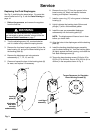
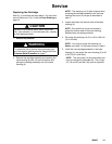
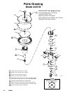
Replacing the Cartridge
See Fig. 3, and follow the steps below. For parts that
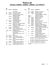
are not called out in Fig. 3, see the Parts Drawing on
page 14.
CAUTION
Handle the hard carbide parts, which are the ball
(16), valve actuator (1), and valve seat (14), carefully
to avoid damaging them.
1. Relieve the pressure.
WARNING
To reduce the risk of serious injury whenever you
are instructed to relieve pressure, always follow the
Pressure Relief Procedure on page 7.
2. Remove the cartridge assembly by loosening the
valve housing (5) with a 6 mm hex wrench and
pulling the cartridge assembly out of the base
housing (4).
NOTE: The retaining nut (3) often loosens when
removing the cartridge assembly from the base
housing. Be sure to re–torque as described in
step 4.
3. Inspect and clean the internal walls of the base
housing (4).
NOTE: Be careful that you do not scrape or
gouge the internal walls of the base housing,
because they are sealing surfaces.
4. Re-torque the retaining nut (3) to 140 to 160 in-lb
(16 to 18 NSm).
NOTE: You must re-torque the retaining nut
before you install it in the base housing in step 5.
5. Install the new cartridge assembly in the base
housing (4), and torque the valve housing (5) to 30
to 35 ft-lb (41 to 48 NSm).
NOTE: The valve seat (14) is double sided and
may be reversed for extended life. The o-rings
(15, 18 and 20) and ball (16) must be replaced.