


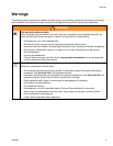
Operation
309498H 13
Operation
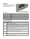
Once the Matrix system is installed, you can verify that
the Transceiver is functioning correctly by observing each
component’s indicator lights. Once verified, no additional
service or maintenance is necessary.
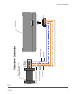
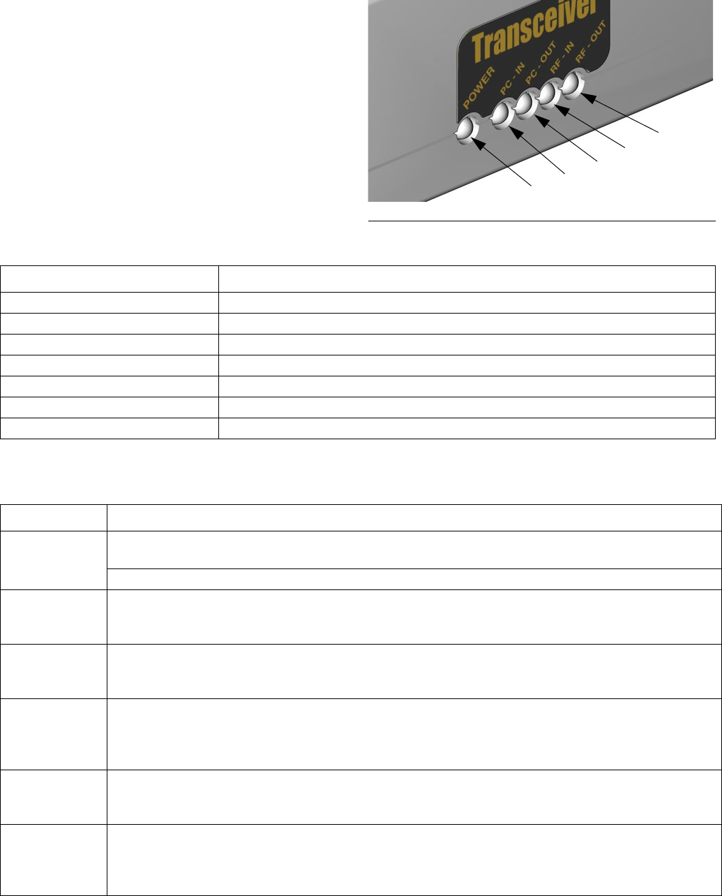
Transceiver See FIG. 13
Transceiver Diagnostics
FIG. 13
J
K
L
M
H
Function Description
Power - Green light (H) When lit, indicates the unit is receiving AC power.
PC IN - Red light (J) Flashing light indicates transmission from the PC to the Transceiver.
PC OUT - Red light (K) Flashing light indicates transmission from the Transceiver to the PC.
RF IN - Red light (L) Flashing light indicates RF signal received from Matrix or other RF source.
RF OUT - Red light (M) Flashing light indicates valid Matrix RF signal data transmitted.
PC IN & RF OUT flashing (J & M) Data from PC is being sent out via RF.
PC OUT & RF IN flashing (K & L) Valid data received by Transceiver and sent to the PC.
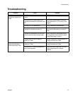
Indicator Diagnostic Definition
No green power
light (H)
Indicates that AC power is not being received. Verify that the power cord is securely plugged into
the component and the AC power outlet.
Verify that the AC power outlet is “live”.
No light on PC
IN (J)
Indicates that the PC is not communicating. Verify that the computer cable is securely plugged into
the back of the Transceiver and the communications port of the PC. Complete the Signal Strength
Test on the Matrix Application screen to verify signal from the PC to the Transceiver.
No light on PC
OUT (K)
Indicates that the Transceiver is not communicating to the PC when receiving information from
other Matrix components. Verify that the RF IN indicator is lit. If lit, verify computer cable is securely
connected. If so, replace Transceiver.
No light on RF
IN (L)
Indicates no transmission is being received by the Transceiver. Components may be too far out of
range for proper RF communications. Verify Matrix components are programmed, have power, are
functioning correctly, and are within RF communication range. Replace Transceiver if all other com-
ponents are working properly and are within appropriate distance.
Constant RF
OUT (M) light
on
System is in a RF communication “lock up”. Applies to all.
No light on RF
OUT (M)
No RF communication transmitted from Transceiver to the Matrix system. Verify that the computer
cable is securely plugged into the back of the Transceiver and the communications port of the PC.
Complete the Signal Strength Test on the Matrix Application screen to verify signal from PC to the
Transceiver and RF OUT from Transceiver.