


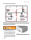
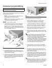
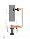
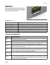
Transceiver Connections
8 309498H
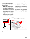
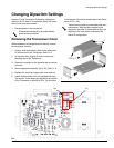
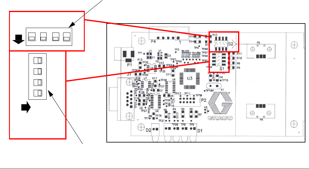
Transceiver Dipswitch Settings
Each is equipped with two, 4 - position dipswitches
labeled S1 and S2. See F
IG. 7.
• Network ID (S1): This is the RF identification
setting assigned to a Matrix installation. All com-
ponents in the system use this same Network
ID. For example, if one dealership is using Net-
work ID (A), the dealership across the street
would required Network ID (B) to avoid RF inter-
ference between the two systems.
• Transceiver ID (S2): This is the RF identifica-
tion setting assigned to a Matrix Transceiver(s).
Matrix system components are then assigned to
the Transceiver(s) ID's as desired for RF com-
munication. For example, If a system required
two Transceivers, some components would be
assigned to one Transceiver and other compo-
nents would be assigned to the second Trans-
ceiver using the Transceiver ID dipswitch.
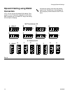
There are (8) Network ID's and (8) Transceiver ID's pos-
sible by changing the position of the dipswitches. The
eight positions are identified as A, B, C, D, E, F, G, and
H.
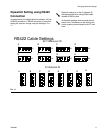
The location of the dipswitches will change based on the
hard-wired connection used between the Transceiver(s)
and PC (RS232 vs. RS422).
The factory default setting for all Transceivers is (AA)
using a RS232 connection. The first A refers to the Net-
work ID and the second A refers to the Transceiver ID. If
multiple Transceivers are used or if RS422 connection is
used, the factory default settings will require changing.
F
IG. 7
Network ID (S1)
Transceiver ID (S2)
12
3
4
S2
on
1
2
3
4
S1
o
n
All dipswitches in down
or off position.
All dipswitches
to right or off
position.
Note: The network ID switch remains
the same with 2 or more transceivers.