


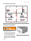

Transceiver Connections
6 309498H
Transceiver Connection/Wiring
There are two connection/wiring options for connecting
the Transceiver(s) to the PC.
• RS232 is for wiring distances of 100 ft (30.5 m) or
less between the Transceiver and PC.
• RS422 is for wiring distances up to 4000 ft. (1219
m) between the transceiver and PC.
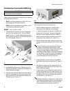
RS232 - 100 ft. (30.5 m) or less.
1. Connect the PC serial port (E) to the Transceiver
serial port (B) using the 100 ft. (30.5 m) RS232
cable (D) (part no. 118346). Do not cut the cable
(D) to remove any excess. Coil excess and place in
out of way location. See F
IG. 4.
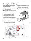
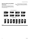
2. Set dipswitch settings on the Transceiver prior to
connecting the power transformer (see page 10 for
RS232 dipswitch settings).
3. Plug the power into the Transceiver power inlet (A)
and into a grounded 120 VAC power source. The
green power light (H) will illuminate indicating the
Transceiver is on. See F
IG. 5.
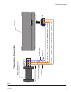
RS422 - wiring distances up to 4000 ft (1219 m).
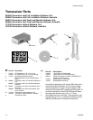
Parts needed to make this connection are:
• RS232 to RS422 converters (119435) will be
required for each Transceiver in the system.
• (1) 249019 Connector kit (includes 10 RS422 con-
nectors and 100 ferrules). To apply the ferrules to
the wires, you will need crimping tool (15B902).
1. Attach the wires to the terminal block on the Con-
verter and on the connector (P4). See F
IG. 6.
2. With the connections made, plug and screw in the
converter to the open serial port (E) on the PC. See
F
IG. 4.
3. Plug and screw in the connector into the RS422
connection located on the transceiver (C). See F
IG.
3.
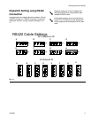
4. Set dipswitch settings on the Transceiver prior to
connecting the power transformer (see page 10 for
RS422 dipswitch settings).
5. Plug the power into the Transceiver power inlet (A)
and into a grounded 120 VAC power source in N.A.
and a grounded 240 VAC power source in Australia.
The green power light (H) will illuminate indicating
the Transceiver is on. See F
IG. 5.
CAUTION
Cable connections and wiring should always be done
prior to powering on the transceiver.
F
IG. 4
D
E
B
F
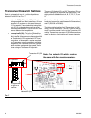
IG. 5
If your PC does not have enough serial ports for
the Matrix Transceiver(s) connections, a USB
converter must be used. Graco recommends using
a 4-port or 8-port Edgeport USB converter
depending on the number of Transceivers required
for connection. These converters are not supplied
by Graco. They can be purchased at B & B Elec-
tronics Manufacturing (www.bb-elec.com).
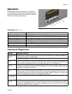
When the transceiver is powered on, it will go into a
test mode and diagnostic light (J) will illuminate for
about 10 seconds then shut-off. During this time
the transceiver is not functional. See F
IG. 5.
A
B
H
J