


Repair
18 309524N
Repair
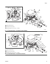
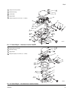
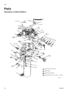
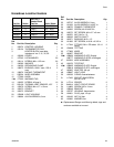
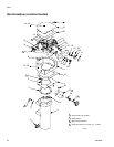
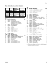
Hazardous Location Heaters: See FIG. 15 & 17
Non-hazardous Location Heaters: See F
IG. 16 & 18
Primary Thermostat & Probe
1. Follow Pressure Relief Procedure, page 14.
2. Remove housing cover (18).
3. Hazardous Location Heater only: Loosen nut (27).
Non-hazardous Location Heater only: Loosen
screws (25).
4. Loosen setscrew (26) in switch shaft (28).
5. Remove screw (16) and bracket (19) holding probe
(EE).
6. Remove wires from the primary thermostat termi-
nals (FF).
7. Pull thermostat probe (EE) out of heater block (3).
Remove thermostat (24) from housing (1).
8. Hazardous Location Heater only: Remove screws
(25).
Non-hazardous Location Heater only: Remove
screw standoff (35) with washer (27).
9. Remove bracket from thermostat (24) and secure to
new thermostat.
10. Liberally apply thermal lubricant (part no. 110009) to
probe (EE) of new thermostat (24). Loop capillary
tube (GG) several times and wrap the loops with tie
strap (42-not shown). Insert probe in the heater
block (3).
11. Continue reassembling in reverse order of disas-
sembly. See Reassembly Notes, below.
Backup Thermostat
1. Follow Pressure Relief Procedure, page 14.
2. Remove housing cover (18).
3. Remove screws (HH) on backup thermostat (10)
tabs, and remove the wires – one from heater block
(3A) and one from line in (9B).
4. Remove the two screws (16), then remove the ther-
mostat (10).
5. Liberally apply thermal lubricant (part no. 110009) to
the bottom of the thermostat (10) and reinstall it in
reverse order of disassembly.
WARNING
Read warnings, pages 4-5. Make sure the main power
is off and heater is cool before repairing.
CAUTION
To avoid damaging capillary tube (GG), which can
cause heater malfunction, do not kink or nick the tube.
To avoid shorting out the heater, do not allow capillary
tube to contact the block terminal (3A). Follow step
10, below.
Reassembly Notes
• Refer to FIG. 15 or 16 for wiring connections.
• Non-hazardous Location Heater only: Make
sure gasket (47) is installed and aligned with
electrical housing screw holes.
• Secure cover (18) with lockwashers (5) and
screws (6 or 52); torque screws to 89 in-lb (10
N•m).