


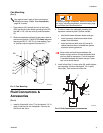
Installation
309524N 7
I
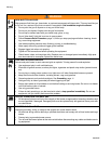
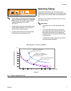
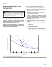
Selecting Tubing
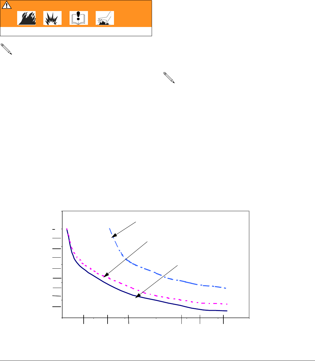
Fluid loses some heat through the tubing or hose
between the heater and spray gun. Locate heater close
to the spray area to minimize heat loss through plumb-
ing.
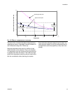
The chart in F
IG. 2 shows a heat loss curve for 3 com-
mon types of tubing.
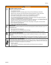
WARNING
Read warnings, pages 4-5.
• Select system components that meet temper-
ature and pressure ratings listed in Technical
Data, page 28. The heater’s normal output
range is adjustable from 84-220°F
(29-104°C).
• Locate heater away from all flammable mate-
rials and where operators will not come in
contact with hot metal surfaces.
• Insulate and/or label lines and components
exiting heater that may become hot.
Chart Notes:
• The greater the flow rate, the less the heat
loss.
• Foam-insulated steel tubing and high pres-
sure airless paint hose retain heat best. Insu-
lated tubing and hose are more expensive,
but higher costs are commonly offset by lower
operating costs.
• Locate heater close to spray area to minimize
heat loss through plumbing.
F
IG. 2: Typical Temperature Drop
0
1
2
3
4
5
6
00.511.522.53
LPM
(GPM)
o
C(
o
F)
(1)
(2)
(3)
(4)
(5)
(6)
(7)
(8)
(9)
(0.1) (0.2) (0.3) (0.4) (0.5) (0.6) (0.7) (0.8)
Heat Loss Curve - 70° F (21° C) ambient
Typical Fluid Temperature Drop
Flow Rate
(20 ft.) 6.1 m steel tube
Fluid: (130° F) 54° C
(20 ft.) 6.1 m steel tube
(3/8 in.) 9 mm foam insulation
Fluid: (110° F) 43° C
(20 ft.) 6.1 m airless paint hose
Fluid: (110° F) 43° C