


Installation
309524N 9
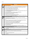
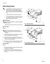
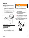
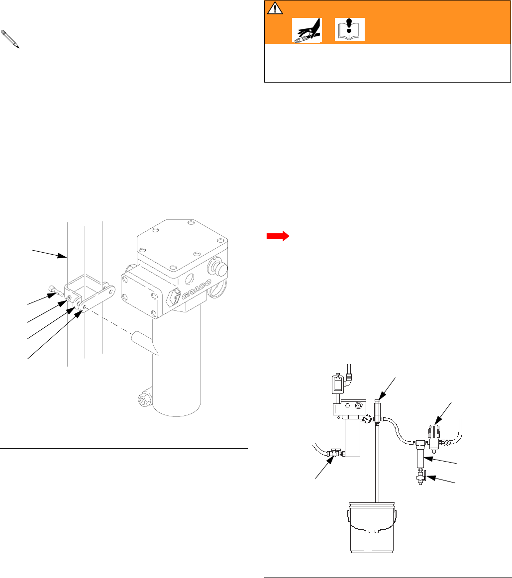
Cart Mounting
(FIG. 5)
1. Place clamps (AA) around the cart vertical post
(DD) and secure to the heater mounting bars (ZZ)
with M8 x 1.25 x 30 mm bolts (6) and lockwasher
(5).
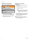
2. Observe temperature ratings for the power cable to
the terminal junction. Cable H07RN does not meet
the required 221°F (105°C). An intermediate Type
“e” junction may be required. Also see F
IG. 7.
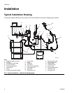
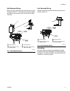
Fluid Connections &
Accessories
(FIG. 6)
1. Install a fluid shutoff valve (T) in the heater’s 1/2-14
npt(m) fluid inlet; do not overtighten. Connect the
fluid line to the valve.
2. Provide a means for adequately handling fluid
expansion caused by heat. Options include:
• Use flexible hoses between heater and gun.
• Install a properly sized accumulator down-
stream from the heater.
• Install a pressure relief valve (X) pre-set to
relieve pressure when it exceeds the system
maximum working pressure.
3. Install a fluid filter (L), drain valve (M), and fluid pres-
sure regulator (N) near the heater’s 1/2-14 npt(f)
fluid outlet. Then connect the fluid line.
You need to have 2 each of cart mounting bar
183485 and clamp 183484. See Accessories,
page 26, to order.
F
IG. 5: Cart Mounting
05543-524
DD
6
5
AA
ZZ
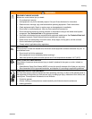
WARNING
To avoid rupturing a component, which can cause seri-
ous injury, including amputation; read warnings, page
4, and follow the instructions below.
Never install a shutoff device between the
heater and gun as this will trap the heated fluid
and not allow for expansion. If a fluid regulator
is installed between the heater and gun, never
use it as a shutoff device.
F
IG. 6: Fluid Connections & Accessories
05545-524
T
X
N
L
M