


Repair
20 309524N
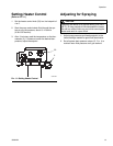
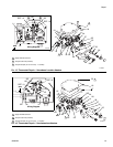
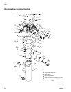
Thermal Limit Sensor
1. Follow Pressure Relief Procedure, page 14.
2. Remove housing cover (18).
3. Remove nut (FF) and nut (3B) holding the leads of
the thermal limit sensor (15) and remove the sensor.
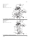
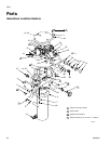
See F
IG. 15 or 16, page 19.
4. Apply thin film of thermal lubricant (part no. 110009)
to the thermal limit sensor (15) bulb and install a
new sensor in the reverse order of disassembly. See
Reassembly Notes, below.
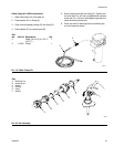
Control Knob
1. Follow Pressure Relief Procedure, page 14.
2. Turn knob (33) to setpoint 1.
3. Loosen setscrew (30) in the control knob (33).
4. Remove control knob (33).
5. Remove adjusting knob (12) from the control knob
(33), and press fit it onto the new control knob.
Check the bushing (29) and replace it if worn.
6. Position new knob (33) so setpoint 1 aligns with
mark (JJ) on the housing (12:00 position) and the
knob is about 1/16 in. (1 mm) away from the hous-
ing. Tighten setscrew (30).
Heater Block
1. Follow Pressure Relief Procedure, page 14.
2. Remove housing cover (18).
3. Hazardous Location Heater only: Remove electrical
junction box cover (4).
4. Hazardous Location Heater only: In the junction box
(1B), disconnect the main power lead from the ter-
minal of the post bushing (9A).
Non-hazardous Location Heater only: Disconnect
the main power lead from the primary thermostat
(24).
5. Hazardous Location Heater only: In the electrical
housing (1A), use a wrench on the flats of the post
bushing (9A) to unscrew it from the housing.
6. See the appropriate sections on pages 18-20 to
remove the primary thermostat and probe (24), the
backup thermostat (10), the thermal limit sensor
(15) and the control knob (33).
7. Remove the 6 screws (6) and lockwashers (5) hold-
ing the housing to the heater block (3).
8. Reassemble heater with the new block (3) in reverse
order of disassembly.
CAUTION
To avoid damaging the capillary tube (GG), which can
cause heater malfunction, do not kink or nick the tube.
To avoid shorting out the heater, do not allow the cap-
illary tube to contact the block terminal (3A).
Reassembly Notes
• Refer to FIG. 15 or 16 for wiring connections.
• Non-hazardous Location Heater only: Make
sure gasket (47) is installed and aligned with
electrical housing screw holes.
• Secure cover (18) with lockwashers (5) and
screws (6 or 52); torque screws to 89 in-lb (10
N•m).