


Air Motor and Throat Service
10 309868D
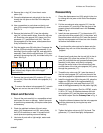
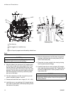
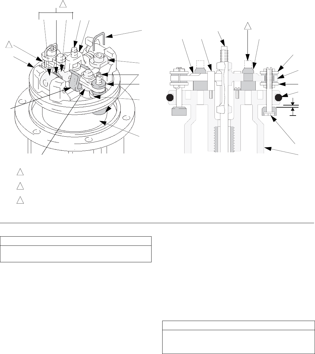
9. Align the holes in the valve nuts (24*) and the slots
on the stems of the inlet valve poppets (32*). Drop
the lock wires (25*) through the holes in the valve
nuts and into the slots in the stems of the inlet valve
poppets. Pull the lock wires down tightly, and bend
the ends with pliers so that they cannot be pulled
back out of the holes.
10. Take the assembly out of the vice so that you can
move it around for steps 11 and 12.
11. Grease and install the new o–rings (13*, 18*, 103*).
12. Install the new u–cup packing (16*) through the bot-
tom of the air motor base, with the lips facing toward
the bottom of the pump.
13. Slide the displacement rod (29) down through the
packings, and lower the air motor piston (34) into
the air motor base (28).
14. Clamp the air motor upright in the vice by closing
the vice jaws below the flange.
15. Carefully lower the air motor cylinder (35) straight
down onto the piston assembly (34). Tighten the six
screws (9) holding the air motor cylinder to the air
motor base (28).
F
IG. 4
0.105 in.
(2.7 mm)
Turn wires up.
Push toggles (L) in and then up.
Cut off tops of poppets as indicated by dotted lines.
1
2
3
32*
24*
25*
23
40
38
20
37
M
17*
27
24*
34
17*
26
40
31*
24*
18*
32*
34
L
24*
1
2
3
Cutaway View
04118
04119
26
31*
CAUTION
Never re-use the old lock wires. They will get brittle
and break easily from too much bending.
CAUTION
To avoid damaging the cylinder wall, lower the cylinder
straight down onto the piston. Never tilt the cylinder as
it is being lowered.