


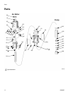

Air Motor and Throat Service
309868D 9
12. Remove the o–ring (18*) from the air motor
piston (34).
13. Clamp the displacement rod upright in the vice by
closing the vice jaws on the flats of the displace-
ment rod.
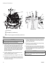
14. Use a screwdriver to push down on the trip rod
yoke (23) to snap the toggle assemblies (L) down.
See F
IG. 4.
15. Remove the lockwires (25*) from the adjusting
nuts (24*) of the transfer valves. Screw the top nuts
off. Screw the valve poppet (32*) stems out of the
grommets (17*) and bottom nuts (24*). Take the
valve poppets off of the stems, and squeeze them
firmly to check for cracks.
16. Grip the toggle arms (38) with pliers. Compress the
springs (20) and swing the toggle assembly (L) up
and away from the piston lugs (M), and remove the
assembly. Check that the valve actuator (27) is sup-
ported by the spring clips (26), but slides easily into
them. See Fig. 4.
17. Remove the trip rod yoke (23), actuator (27), and
trip rod (40). Check the exhaust valve poppets (31*)
for cracks.
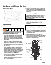
Clean and Service
1. Clean all the parts carefully in a compatible solvent
and inspect for wear or damage. Use all the repair
kit parts during reassembly, and replace other parts
as necessary.
2. Check the polished surfaces of the air motor
piston (34), displacement rod (29), and cylinder
wall (35) for scratches or wear. A scored rod will
cause premature packing wear and leaking.
3. Lubricate all parts with a light weight, water-resis-
tant grease.
Reassembly
1. Clamp the displacement rod (29) upright in the vice
by closing the vice jaws on the flats of the displace-
ment rod.
2. Pull the new exhaust valve poppets (31*) into the
valve actuator (27), and clip off the top parts of the
poppets (shown with dotted lines in the Cutaway
View in Fig. 4).
3. Install the new grommets (17*) in the actuator (27),
place the inlet valve poppets (32*) in the piston, and
thread the bottom valve nuts (24*) onto the stems of
the inlet valve poppets until there are a few threads
left before the threads run out.
4. Grease heavily and place the trip rod (40) in the air
motor piston (34), place the actuator (27) in the
yoke (23), and place the well–greased actuator/yoke
assembly in the piston, with the trip rod going
through the center holes of the actuator and yoke
and the stems of the inlet valve poppets (32*) going
through the grommets (17*).
5. Thread the top valve nuts (24*) onto the stems of
the inlet valve poppets (32*) until one thread of the
inlet valve poppets is exposed above the valve nuts.
6. Install the toggle pins (36) in the yoke (23), place the
toggle arm (38) ends of the toggle assembly (L)
onto the toggle pins, and snap the pivot pin (37)
ends of the toggle assembly into the piston lugs (M).
7. Measuring with the gauge (Part No.15E796), create
0.105 in. (2.7 mm) of clearance between the inlet
valve poppets (32*) and the piston seat when the
inlet valve is open. See the Cutaway View in Fig. 4.
8. Tighten the bottom valve nuts (24*) by hand. The
grommets (17*) should be slightly compressed.
To reduce the risk of pinching or amputating your fin-
gers, always keep fingers clear of the toggle
assemblies (L).
To remove the exhaust valve poppets (31*), stretch
them out and cut the end off with a sharp knife.
If you thread the valve nuts too far down onto the
poppets, they will run off the threaded part of the
poppets.
Adjust the distance between the inlet valve poppets
and the piston seat by turning the top valve
nuts (24*).