


Repair
17
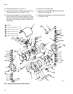
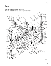
Repair the Air Valve
Disassembly
1. Prepare the pump for repair, page 14.
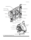
2. Remove the screws (31) from one fluid cover (1).
Pull the cover assembly off, separating it from the
fluid tubes (12). See F
IG.7.
3. Remove the screws (31) and the other fluid cover
(1) assembly, keeping the fluid tubes (12) attached.
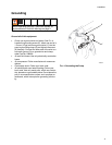
4. Remove the air inlet fitting (40).
5. Remove the screws (68) and the top (67) and bot-
tom (66) covers.
6. Remove the diaphragms (14), page 15.
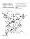
7. Remove the four screws (38) and washers (37), air
valve cover (36), and gasket (35).
8. Pry the air valve seat (33) out of the housing (5),
using two screwdrivers inserted in the recesses on
the seat. Remove the o-rings (43, 44, and 80) from
the seat.
9. Remove the cup (47) from the center housing.
10. Remove the two clips (46) from the shaft (17).
11. Remove the screws (30), cylinder outer cover (11),
and cylinder (7). Do not lose the o-rings (22).
12. Pull out the piston (16) and shaft assembly.
13. Remove the screws (29) and inner cover (6).
14. Remove the clips (50) from the air valve plugs (51).
Thread a screw (38) partially into each plug and pull
the plugs out. Remove the o-rings (52).
15. Push the driver carriage (48) out of its bore.
Remove the o-rings (49).
16. Remove the clips (21) and push the bearings (18)
out of the center housing (5), inner cover (6), and
outer cover (11). Remove the o-rings (19, 20) from
the bearings.
17. Remove the carriage (45).
Reassembly
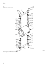
1. Install the o-rings (19†, 20†) on the three bearings
(18). Install the bearings in the center housing (5),
cylinder inner cover (6), and cylinder outer cover
(11). Secure with the clips (21).
2. Install the carriage (45) in the center housing (5),
oriented as shown.
3. Install the o-rings (49†) on the driver carriage
(48†).Push the driver carriage into its bore, oriented
as shown.
4. Install the o-rings (52†) on the air valve plugs (51).
Install the plugs and secure with clips (50).
5. Check that the o-rings (42 and 28) are in place in
the center housing (5).
6. Check that the o-rings (22 and 25) are in place on
the cylinder inner cover (6).
7. Check that the o-ring (23), packing (26), and quad
ring (32) are in place on the piston (16).
8. Insert the air valve tube (24) through the cylinder
inner cover (6). Install the cover on the center hous-
ing (5). Seat the air valve tube securely in the center
housing, oriented with the spring pin (27). Torque
the screws (29) to 8 N•m (5.9 ft-lb).
9. Lubricate the diaphragm shaft (17), then slide it into
the center housing (5), guiding the air valve tube
(24) through the hole in the piston. Install the two
clips (46) on the shaft.
10. Liberally grease the inside of the cylinder (7) and
the piston o-ring (23). Install the cylinder, making
sure it is seated on the inner cover (6).
11. Install the o-ring (22) on the cylinder outer cover
(11). Install the outer cover. Torque the screws (30)
to 15 N•m (11 ft-lb).
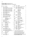
Air Valve Repair Kit 243153 is available. Parts
included in the kit are marked, for example (33†).
For the best results, use all parts in the kit.
Lubricate all o-rings when reassembling the
pump.