


8
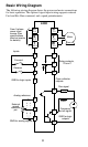
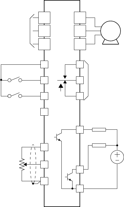
Basic Wiring Diagram
The following wiring diagram shows the power and motor connections
for basic operation. The optional signal input wiring supports external
Fwd and Rev Run command, and a speed potentiometer.
(L1)
R
(L2)
S
(N/L3)
T
(T2)
V
(T3)
W
(T1)
U
Motor
Forward
L
O
H
Reverse
Relay contacts,
1 Form C
Run signal
Frequency
arrival signal
Open collector
outputs:
External
speed
reference
pot.
L200
From 3-phase
power input
source (See
specifications
label on inverter
for details)
Load
Load
Analog reference
PCS
2
1
CM2
12
11
AL0
AL1
AL2
Inputs:
L
GND for logic inputs
GND for logic
outputs
GND for analog signals