


3
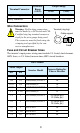
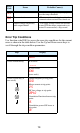
Wire Connectors
Warning: Field wiring connections
must be made by a UL Listed and CSA
Certified ring lug terminal connector
sized for the wire gauge being used.
The connector must be fixed using the
crimping tool specified by the con-
nector manufacturer.
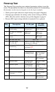
Fuse and Circuit Breaker Sizes
The inverter’s input power wiring must include UL Listed, dual-element,
600V fuses, or UL Listed, inverse-time, 600V circuit breakers.
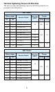
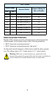
Terminal Connector
Wire Size
Range
(AWG)
Torque Range
ft-lbs (N-m)
Logic/Analog connector 30—16 0.16—0.19 0.22—0.25
Relay connector 30—14 0.37—0.44 0.5—0.6
200V Models
Motor output
Inverter Model
Ampere Rating for
Fuse or Breaker
kW HP
0.2 1/4 –002NFE(F)2/NFU2 10
0.4 1/2 –004NFE(F)2/NFU2 10
0.55 3/4 –005NFE(F)2 10
0.75 1 –007NFE(F)2/NFU2 15
1.1 1 1/2 –011NFE(F)2 15
1.5 2 –015NFE(F)2/NFU2 20 (single ph.)
15 (three ph.)
2.2 3 –022NFE(F)2/NFU2 30 (single ph.)
20 (three ph.)
3.7 5 –037LFU2 30
5.5 7 1/2 –055LFU2 40
7.5 10 –075LFU2 50
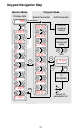
Terminal (ring lug)
Cable support
Cable