


12
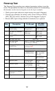
Powerup Test
The Powerup Test procedure uses minimal parameter settings to run the
motor. The procedure describes two alternative methods for commanding
the inverter: via the inverter keypad, or via the logic terminals.
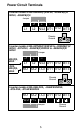
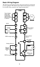
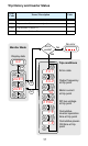
• Check power input and motor output wiring (see page 8 diagram).
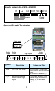
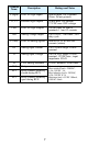
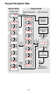
• If using logic terminals for testing, verify correct wiring on [PCS],
[FW], [H], [O], and [L] (bottom row) per the diagram on page 8.
• Reverse [RV] input wiring (defaults to terminal [2]) is optional.
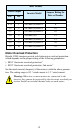
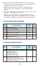
Step Description Via Keypad
Via Logic
Termi nal s
1 Set speed command
source setting
A001 = 00
(keypad pot.)
A001 = 01,
[H–O–L] input
2 Set Run FW command
source
A002 = 02
(Run key)
A002 = 01,
[FW] input
3 Set Run REV command
source
— C002 = 01,
[RV] input
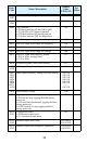
4 Set motor base freq. A003 = 60
5 Set motor poles
(2 / 4 / 6 / 8)
H004 = 4 (default), change only if
your motor is different
6 Set keypad display to
monitor freq.
Access D001, press Func. key, display
will show
0.0
Perform safety check Disconnect load from motor
7 Turn keypad pot.
to MIN position
Ensure voltage on
[O]—[L] termi-
nals= 0V
8 Run Forward command Press Run key Turn ON the
[FW] terminal
9 Increase speed Rotate keypad
pot. CW dir.
Increase voltage
at [O]
10 Decrease speed Rotate keypad
pot. CCW dir.
Decrease voltage
at [O]
11 Stop motor Press Stop key Turn OFF the
[FW] terminal
12 Run Reverse command
(optional)
— Turn ON the [RV]
terminal
13 Stop motor — Turn OFF the
[RV] terminal