


INTRODUCTION
This service manual describes the latest service information
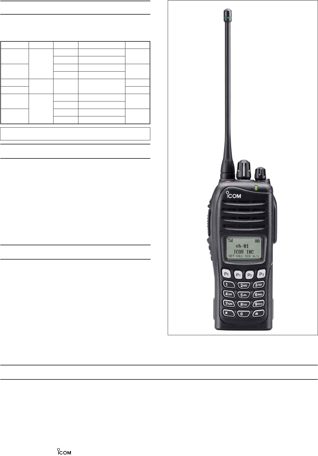
for the
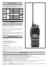
IC-F4061T/S, IC-F4062T/S and IC-F4063T/S UHF
TRANSCEIVERS
at the time of publication.
ORDERING PARTS
Be sure to include the following four points when ordering
replacement parts:
1. 10-digit Icom parts number
2. Component name and informations
3. Equipment model name and unit name
4. Quantity required
<SAMPLE ORDER>
5030002830 LCD M4-0078TAY-2 IC-F4061S Front unit 5 pieces
8810009220 Screw
PH B0 M2×8 ZK (BT)
IC-F4061S Chassis 10 pieces
Addresses are provided on the inside back cover for your
convenience.
REPAIR NOTES
1. Make sure the problem is internal before disassembling the transceiver.
2. DO NOT open the transceiver until the transceiver is disconnected from its power source.
3. DO NOT force any of the variable components. Turn them slowly and smoothly.
4. DO NOT short any circuits or electronic parts. An insulated turning tool MUST be used for all adjustments.
5. DO NOT keep power ON for a long time when the transceiver is defective.
6. DO NOT transmit power into a signal generator or a sweep generator.
7. ALWAYS connect a 30 dB to 40 dB attenuator between the transceiver and a deviation meter or spectrum analyzer when
using such test equipment.
8. READ the instructions of test equipment thoroughly before connecting equipment to the transceiver.
To upgrade quality, all electrical or mechanical parts and internal
circuits are subject to change without notice or obligation.
Icom, Icom Inc. and logo are registered trademarks of Icom Incorporated (Japan) in the United States, the United
Kingdom, Germany, France, Spain, Russia and/or other countries.
NEVER connect the transceiver to an AC outlet or to a DC
power supply that uses more than 7.2 V. Such a connection
could cause a fire or electric hazard.
DO NOT expose the transceiver to rain, snow or any liquids.
DO NOT reverse the polarities of the power supply when
connecting the transceiver.
DO NOT apply an RF signal of more than 20 dBm (100 mW)
to the antenna connector. This could damage the trans-
ceiver's front end.
CAUTION
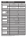
MODEL Version Symbol Frequency Key Pad
IC-F4061T
U.S.A
[USA-01] 400–470 MHz
10-key
[USA-02] 450–520 MHz
IC-F4061S
[USA-01] 400–470 MHz
4-key
[USA-02] 450–520 MHz
IC-F4062T
EURO [EUR-01] 400–470 MHz
10-key
IC-F4062S 4-key
IC-F4063T
GENERAL
[GEN-01] 400–470 MHz
10-key
[GEN-02] 450–520 MHz
IC-F4063S
[GEN-01] 400–470 MHz
4-key
[GEN-02] 450–520 MHz