


6 - 6
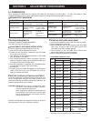
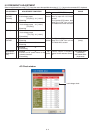
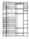
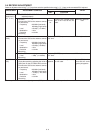
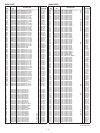
5-4 RECEIVE ADJUSTMENT
Select an adjustment item using [
↑
] / [
↓
] keys, then set to the specifi ed value using [
←
] / [
→
] keys on the connected PC’s keyboard.
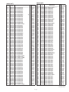
ADJUSTMENT ADJUSTMENT CONDITION
MEASUREMENT
VALUE
UNIT LOCATION
RECEIVE
SENSITIVITY
[BPF C ALL]
NOTE:
“RECEIVE SENSITIVITY” must be adjusted before “S-METER.” Otherwise, “S-METER” will not be
adjusted properly.
1
• Channel : 1
Multi
connec-
tor
Connect the SINAD meter
with an 8
Ω
load to the JIG
cable.
Minimum distortion
level
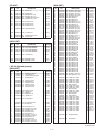
• Connect the SSG to the antenna connec-
tor and set as;
Frequency
Level
Modulation
Deviation
• Receiving
: 400 MHz (low band)
450 MHz (High band)
: +20 dBµ
†
(–87 dBm)
: 1 kHz
: ±3.5 kHz
S-METER
[RSSI]
1
• Channel : 1 Push the [ENTER] key on the connected PC’s keyboard to set
“S3” level.
• Connect the SSG to the antenna connec-
tor and set as;
Frequency
Level
Modulation
Deviation
• Receiving
: 400 MHz (low band)
450 MHz (High band)
: +23 dBµ
†
(–84 dBm)
: 1 kHz
:
±
3.5 kHz
2
• Set the SSG as;
Level
• Receiving
: –7dBµ
†
(–114 dBm)
Push the [ENTER] key on the connected PC’s keyboard to set
“S1” level.
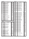
SQUELCH
[SQL]
1 • Channel : 1 External
speaker
Connect an 8
Ω
speaker to
the JIG cable.
Set the [SQL] to the
value that the audio
signals just appears.
• Close the squelch by adjusting the value of
[SQL] item on the CS-F3060 ADJ’s screen.
• Connect the SSG to the antenna connec-
tor and set as;
Frequency
Level
Modulation
Deviation
• Receiving
: 400 MHz (low band)
450 MHz (High band)
: –14 dBµ
†
(–121 dBm)
: 1 kHz
:
±
3.5 kHz
†;
The output level of the standard signal generator (SSG) is indicated as the SSG’s open circuit.