


30
12
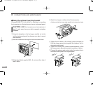
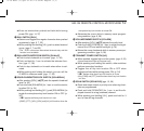
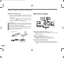
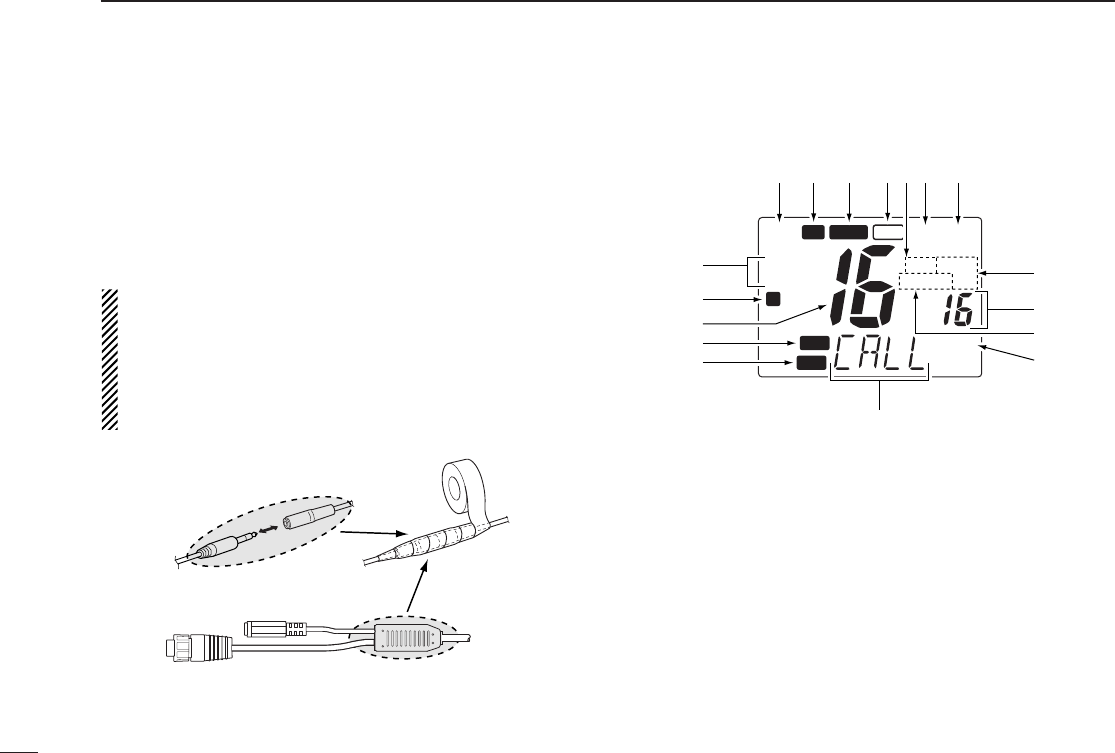
HM-134 REMOTE-CONTROL MICROPHONE
!1 EXTERNAL SPEAKER JACK
➥Connect the external speaker (
an 8 Ω load)
. The internal
speaker can be deactivated via the Set mode program-
ming. (p. 37)
•The speaker output employs a BTL (Balanced Trans-
Less) circuit, NEVER connect the speaker cable to
ground (or chassis). Use a floating setup.
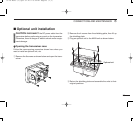
CAUTION: After connecting the external speaker jack,
cover the jack with water resistant tape as shown below to
avoid water seeping into the microphone.
Binding the mic-cable and external-speaker jack connec-
tion mold with water resistant tape increases the water-
proofing of the connection mold.
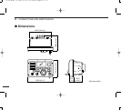
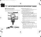
■ Function display
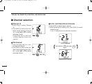
q CHANNEL GROUP INDICATOR (pgs. 6, 32)
Indicates whether an International (INT) or U.S.A. (USA)
channel is selected.
w KEY LOCK INDICATOR (p. 34)
➥Appears while the key lock function is in use.
➥Flashes while the all key lock function is in use.
e CHANNEL NUMBER READOUT
➥Indicates the selected operating channel number. “A”
appears when a simplex channel is selected. (pgs. 6,
32)
CALL
DUP
P SCAN
SCRM
TRI
DUAL
LOW
TAG
USA
INT
L
TX
BUSY
VOL
SQL
q
w
r
t
e
!6 !5 !2!3 !1
!0
o
i
u
y
!4
WAIT
!7
External SP jack
Connection mold
01 IC-M503-(1).qxd 01.12.17 5:00 PM Page 30 (1,1)