


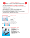
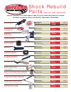
Tools You Will Need
You will need to have the following additional tools/equipment to re-valve
our dampers:
1. Nitrogen tank. The tank can be purchased at a local gas supply
store. A small 40 lb. tank will likely last you for a full season.
2. 350 PSI pressure regulator. Be sure that the regulator is compatible
with the nitrogen gas.
3. High pressure hose to interface with pressure regulator and the
charging valve assembly
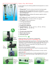
4. 0-6" calipers with English (imperial) units of measurements
5. Torque wrench with a minimum of 216 in-lb. capacity
6. 1/2" socket for above torque wrench
7. 11/16" open-end wrench
8. 1/2" boxed end wrench
9. Charging valve assembly
10. Assorted drill bits - .025” dia., .031” dia., .040” dia., .055” dia.,
.062” dia., .076” dia., and .094” dia.
11. Paint strainers
12. Tire valve core removal tool
13. Bicycle style tire pump
14. Graduated Cylinder
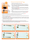
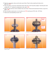
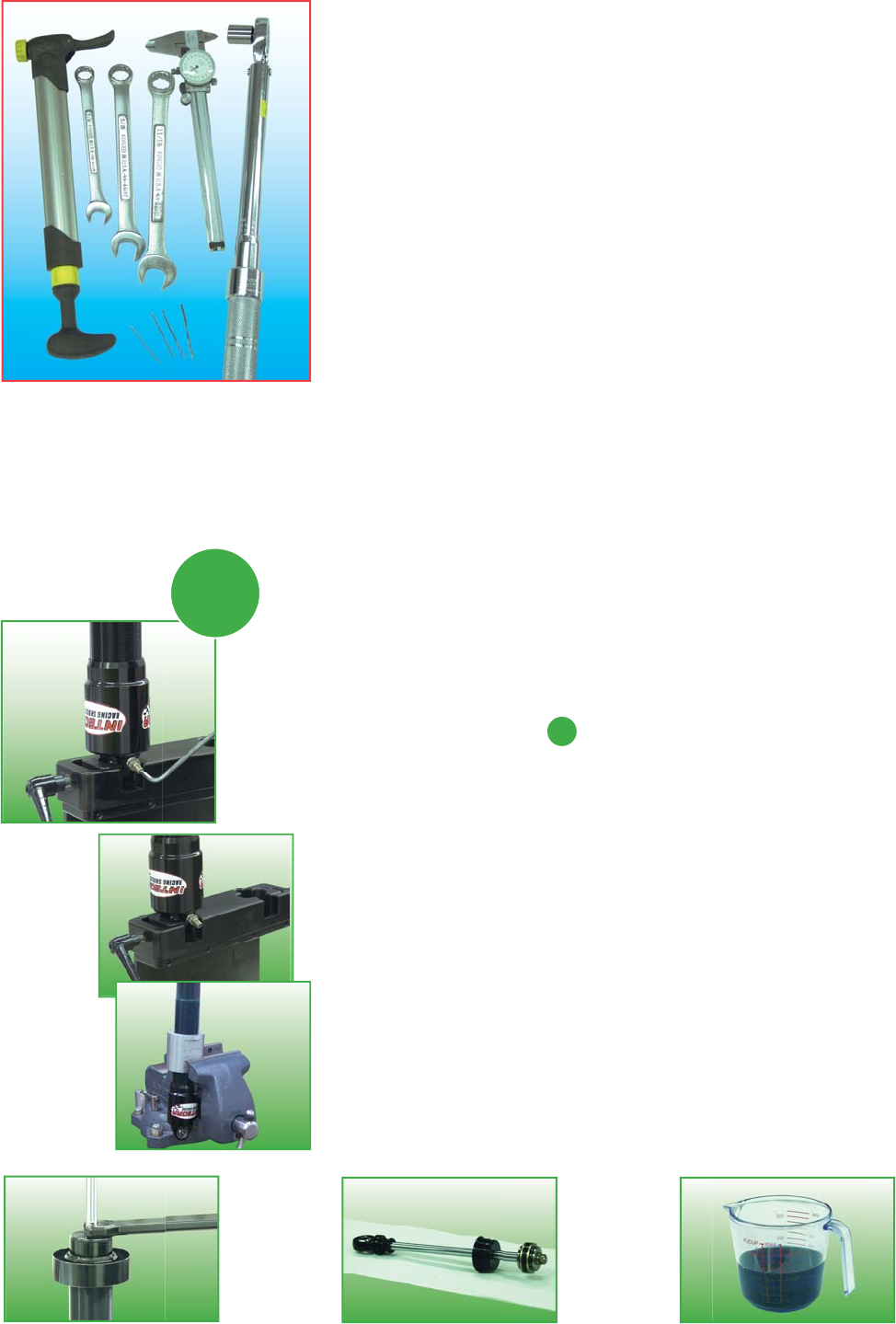
Disassembly
• Clean the exterior of the shock prior to disassembly.
• Discharge nitrogen gas prior to disassembly (A1).
• Clamp the body of the shock (rod end up)
(A2) using the Integra Shock
Vise (part # 310-30204). Alternately, you can use a standard vise, using
body clamps (part # 310-30311, purchased separately). Do not over-
tighten clamps. Permanent deformation of the tube will occur if the
clamps are over-tightened.
• Be sure the rod is completely extended.
• Using the rod guide wrench provided, loosen the rod guide and slowly
remove the head assembly
(A3).
• Place the head assembly you have just removed on a clean, low lint
paper towel
(A4).
• Pour the oil into a measuring cup, or similar graduated cylinder. Use a
paint strainer to ensure that any large, foreign particles are removed
from the oil
(A5).
A1
Discharge
nitrogen
gas prior to
disassembly
A2
Clamp
the body
of the shock
A3
Loosen the
rod guide and
slowly remove
the head
assembly
A
A
A4
Place head
assembly on
low lint paper
towel
A5
Place oil into
a measuring
cup