


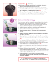

Assembly
C
• Be sure all seals are lubricated with O-ring lube prior to assembling the
unit.
• Once the head assembly has been completely built, the damper can be
assembled as follows:
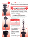
1. Clamp the body of the shock in the vice.
NOTE:
When setting the fl oating piston to the proper height,
be sure not to use a high volume pressure source
such as an air compressor or compressed air bottle.
SERIOUS INJURY COULD OCCUR !!!!!!!!
! !
2. Using the fl oating piston height tool, set the fl oating piston to the
proper setting. Remove valve core from tank valve. Use a bicycle
style tire pump to “bump” the fl oating piston approximately half way up
into the tube. Set the fl oating piston height tool for the proper damper
length. See chart for proper setting.
NOTE:
Be sure not to use a hard device to measure or adjust
the fl oating piston height, as this may cause scratches in the I.D.
of the shock body that could alter the proper performance of the shock.
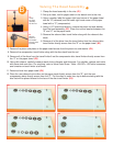
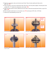
3. Seat the tool fully into the fl oating piston from the top of the
disassembled shock body. (C1)
4. Press the tool into the shock body
until the fl oating piston reaches the
proper height. Reinstall the valve
core into the tank valve. (C1)
5. Pull the rod guide approximately
half way down the piston rod (C2).
6. Fill shock body with oil to the
bottom of the internal threads
(C3).
7. Slowly install the head assembly
into the shock body. Allow time for
the air below the piston assembly
to “bleed” past.
8. Stroke the head assembly until
the air below the piston has
completely vented to the top of the
shock body. Be sure the fl oating
piston does not move.
(C4)
C3
C2
C4
C1
Body Distance from
Length top of tube to Center
of fl oating piston
9” 10 5/8”
8” 9 13/16”
7” 8 15/16”
6” 8”
5” 7 1/8”
C